MSD/GM HEI Coils

1991 Miata w/ Link ECU: MSD/GM coil packs

Wiring procedure:

DSCF0002.JPG (237097 bytes) First of all, disconnect the power from the battery.

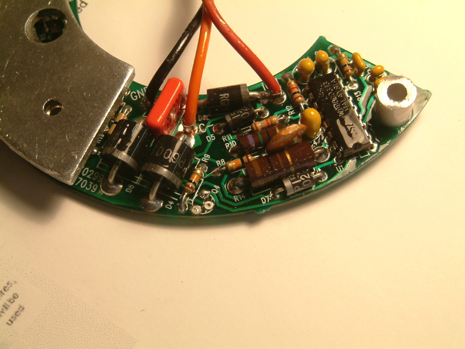
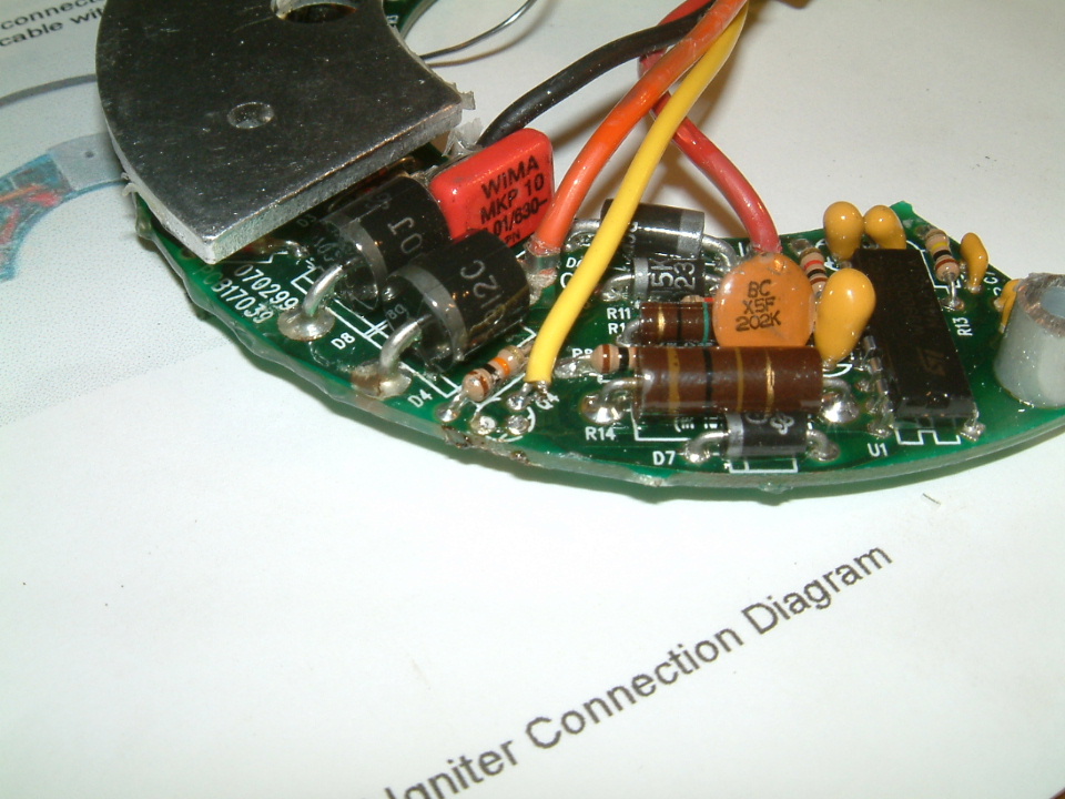
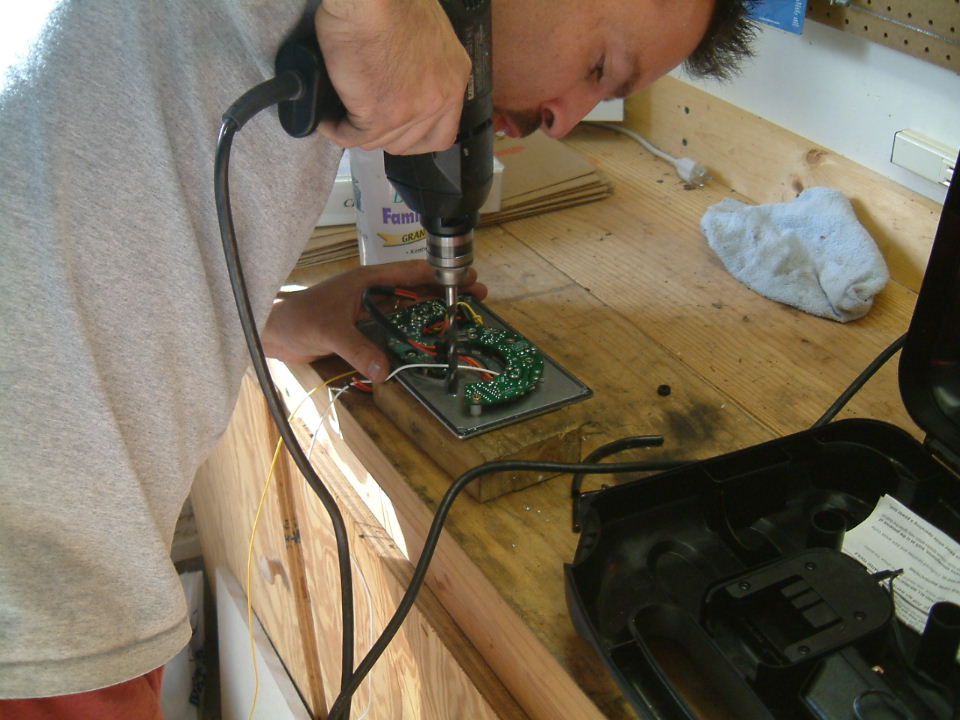
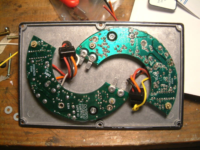
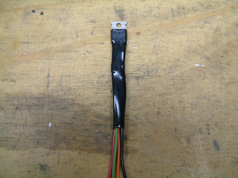
Transistor 'Q4' must be removed from each of the new MSD igniters.  Using a soldering iron, a solder sucker (more on that later) and an extra set of hands with pliers to pull out the transistor, it came right out.  The metal mounting standoff on the right side of this image was also trimmed down by about 1/4 inch so that the igniter heat sink (big metal part on left of image) can mount flat against the mounting case.

DSCF0005.JPG (233234 bytes) A 22 gauge wire is soldered into the hole furthest away from the edge of the board where the transistor was removed.

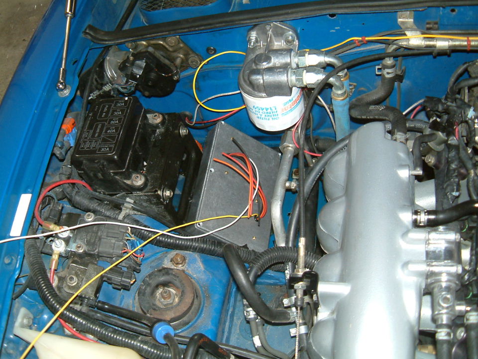
For the 1-4 cylinder coil igniter, we used a yellow wire.
For the 2-3 cylinder coil igniter, we used a white wire.

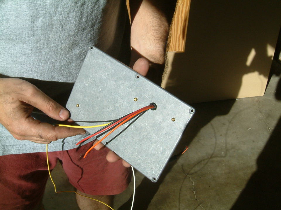
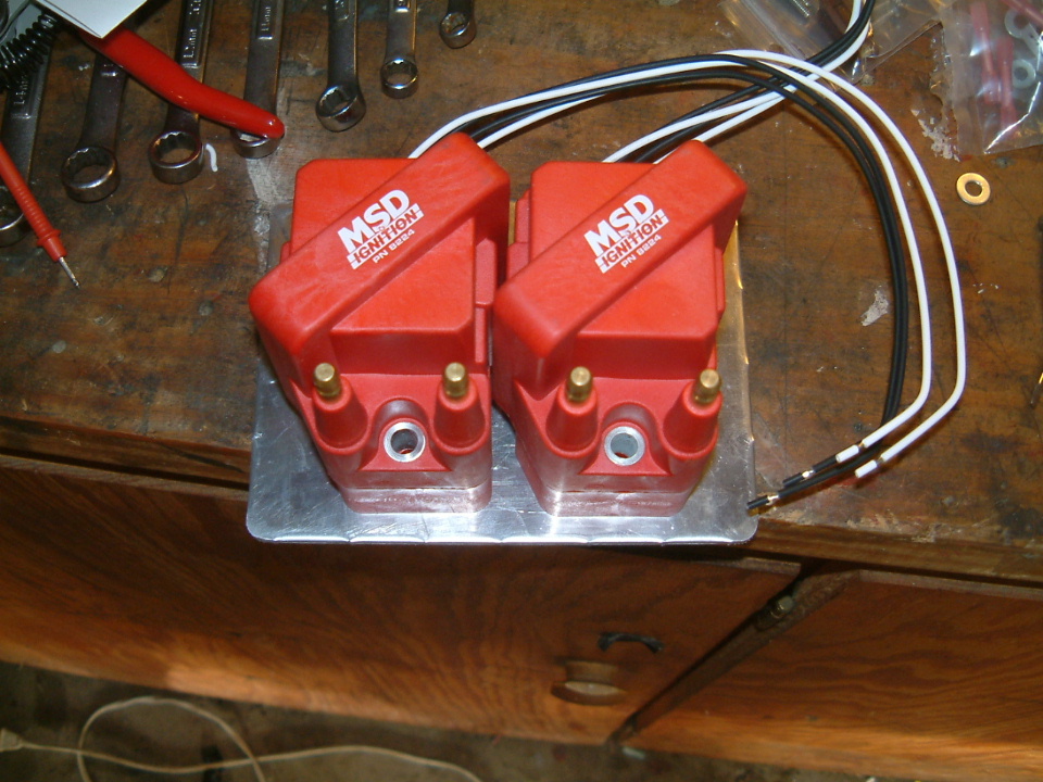
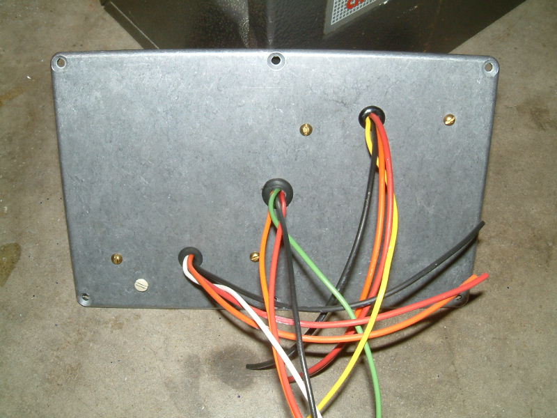
On each igniter, there is a connector with a red, orange and black wire.  Cut off the connector but leaving the full length of the wires.

DSCF0015.JPG (112897 bytes) The metal casing for the igniters needs to be water proof and dissipate heat from the igniter transistors.  We chose to mount the igniters to the lid of the casing and run the wires through the lid as well.  
DSCF0014.JPG (107506 bytes) After drilling the holes for the wires, we used rubber grommets to protect the wires from the sharp edges and neaten up the installation.  Silicone sealant is used to seal the wires around the grommets.
DSCF0035.JPG (124095 bytes) Here is a shot of the modified igniters mounted to the lid with wires passing through.
DSCF0029.JPG (269734 bytes) The igniter coils come with a heat conductive paste that is spread over the heat sinks before mounting to the coil.  When properly mounted the heat sinks should be flush against the metal casing.
DSCF0031.JPG (241010 bytes) Here is the front side of the lid showing the wires from each igniter passing through.
DSCF0013.JPG (120630 bytes) The location for this install will be in place of the windshield washer bottle on the passenger side.  We want to keep using the remote oil filter mount so both the igniter case and coils need to be carefully located.
DSCF0018.JPG (152615 bytes) The casing fits nicely in this area.  There is one existing bolt that we removed and replaced with a longer one and used that to mount the casing down.  We used a rubber washer on the inside of the casing to seal this bolt hole.  We also ran a strip of weather stripping foam along the bottom edge of the casing since there is only one bolt (we thought it might rattle some). 
DSCF0021.JPG (158888 bytes) Here is the lid temporarily placed in the casing.  We pretty much wrapped it up for the day at this point.  Not hard work, but just going carefully.
DSCF0032.JPG (278140 bytes) Here are the two MSD coils sitting on MSD bases.  Test fitting potential locations.
DSCF0033.JPG (282616 bytes) Here's another coil shot.  The metal plate should fit nicely where the washer bottle was.
DSCF0022.JPG (76723 bytes) Remember that solder sucker in the first step, it works well cleaning out nostrils too!  Yep, when I start goofing off, it's definitely a good sign to wrap things up for another day.
DSCF0023.JPG (175293 bytes) Mike smiles just before he speeds away in fright from me and my solder sucker.
DSCF0024.JPG (198482 bytes) Bye Mike!!!  Come back soon!
tachmod1.JPG (95060 bytes) Back at it another day...

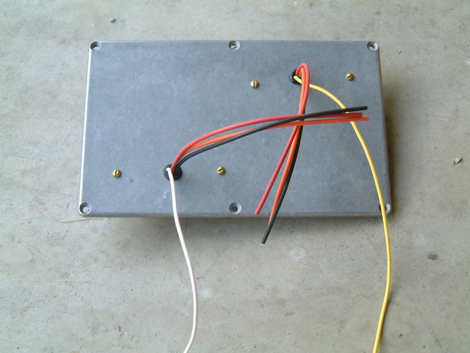
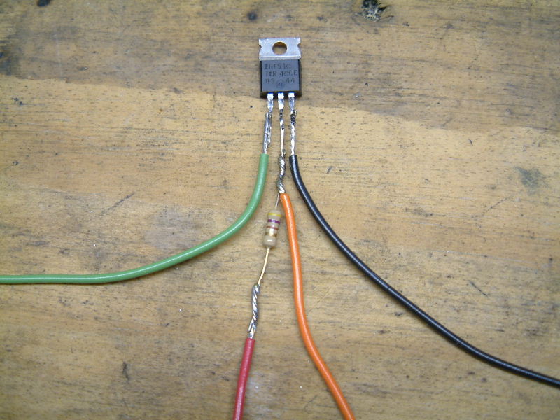
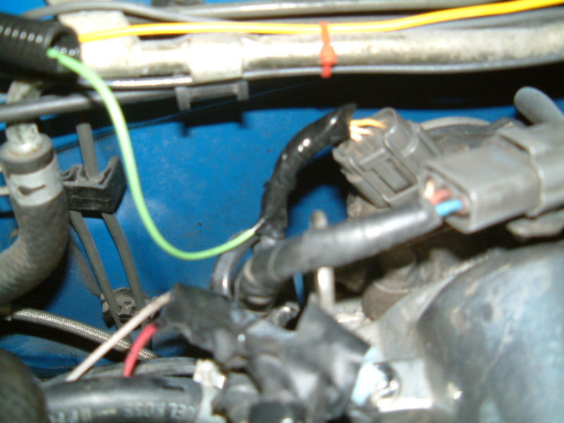
Since the tachometer on 90-93 miatas run from a signal generated at the OEM igniter (now removed), we have to hook up a small circuit in place of it.  The circuit consists of one MOSFET transistor, one 470 ohm resistor and four different color 20 or 22 gauge wires.  I chose green, red, orange and black.

The wiring diagram for this circuit and how to hook it up is shown by clicking here.

tachmod2.JPG (87847 bytes) Seal up the circuit with heat shrink tubing or electrical tape.  Note, the flat metal heat sink of this transistor also carries the "drain" of the circuit.  Although this image doesn't show it, this needs to be covered too so it doesn't short out.
coil13.JPG (91062 bytes) Choose a place to position the transistor circuit.  We chose to locate the circuit inside the igniter case (again, take note shield the transistor base - we grounded it out at first and it kept the tach from working).  The wires for out transistor circuit are fed out the center hole of the case.
Time to hook it all up.  There are several wires in the original igniter harness that can be used and are conveniently located near the area we chose to mount our igniter case.
coil14.JPG (124166 bytes)


coil15.JPG (103684 bytes)


coil19.JPG (75481 bytes)


coil16.JPG (126048 bytes)

1) +12Vdc Connection: Locate the blue wire at the OEM igniter harness.  Tap into this wire and connect the following:

-One of the two white wires coming from EACH of the MSD coil mounts (btw, the black wires are not used).

-The red wires coming from each igniter.

-The single red wire coming from the transistor circuit.

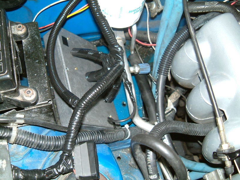
2) Ground: Run a black 14 gauge wire or larger from the connection of where the battery ground ties into the PPF all the way to the igniter box area.  This is to ensure a good ground for the new igniters and tach circuit.  Connect this wire to the following:

-The black wires coming from each igniter.

-The single black wire coming from the transistor circuit.

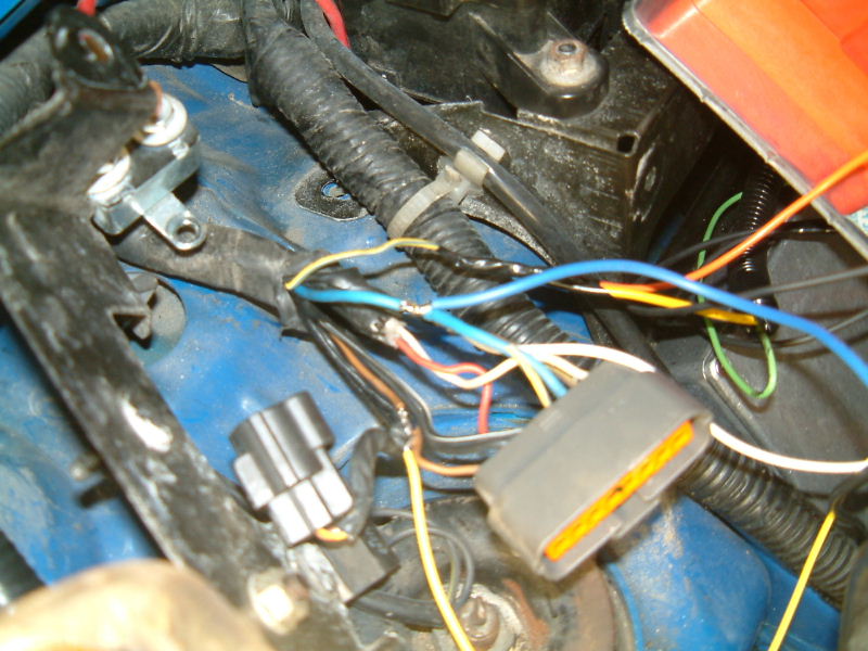
3) Igniter input signals:

-Connect the white 22 gauge wire coming from the 1-4 igniter to the brown/yellow wire in the original igniter harness.

-Connect the yellow 22 gauge wire coming from the 2-3 igniter to the brown wire in the original igniter harness.

4) Igniter output signals:

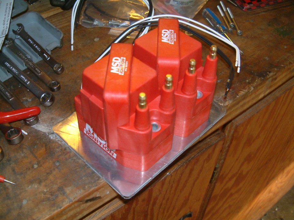
-Connect the 1-4 igniter orange wire to one of the white wires of the coil mounts.  This coil will generate a spark on plugs 1 and 4.

-Connect the 2-3 igniter orange wire to one of the white wires of the coil mounts.  This coil will generate a spark on plugs 2 and 3.

5) Signal from CAS:

-Connect the green wire from the transistor circuit to the white wire in the CAS harness.  This wire carries 5V pulses from the CAS which will be stepped up to drive the tach near 12V pulses.

6) Signal to tach:

-Run the orange wire from the transistor circuit through the firewall and under the dash over to the tach.  Find the yellow/blue leading to the tach.  Cut this wire.  Connect the orange wire to the yellow/blue wire going to the tach.

*Note: We originally connected the orange wire to yellow/blue wire at the OEM igniter harness.  This fed the tach signal to the tach, but somehow caused some strange readings at the FM/Link ECU.  The ECU uses an air temperature sensor and the A/T signal bounced around intermittently when the tach connection at the OEM igniter was made.  We noticed this because when the engine is under boost, if the intake temperature exceeds the AT limit setting, the engine cuts off much like a rev limiter.  This problem was eliminated by running the orange wire all the way to the tach as a dedicated line.

Test all connections then neaten up the wiring.

coil17.JPG (118868 bytes)
coil18.JPG (133553 bytes)
Mount the coils and attach plug wires.  Hook up the power to the battery, say a prayer and start the engine.