This page is
an overview of my V8 conversion project. I have had a turbocharger
of some form on my miata for about 10 years; while it has been a blast
to drive, the V8 bug has bitten hard and so now I'm entering a new phase
for my miata. The engine going in will be the result of influences from my friends on
miata.net
and other Ford forums, friends in the local miata community, friends at work, local
machine shops/garages/speed shops, and basic research from reading up on
302 Windsor based blocks. My basic goal is to achieve at least
325hp to the ground (about 375 at the crank) while equipping the car for decent street manners
yet reliable enough to withstand occasional track time. Oh... and
it's gotta have that classic V8 sound.
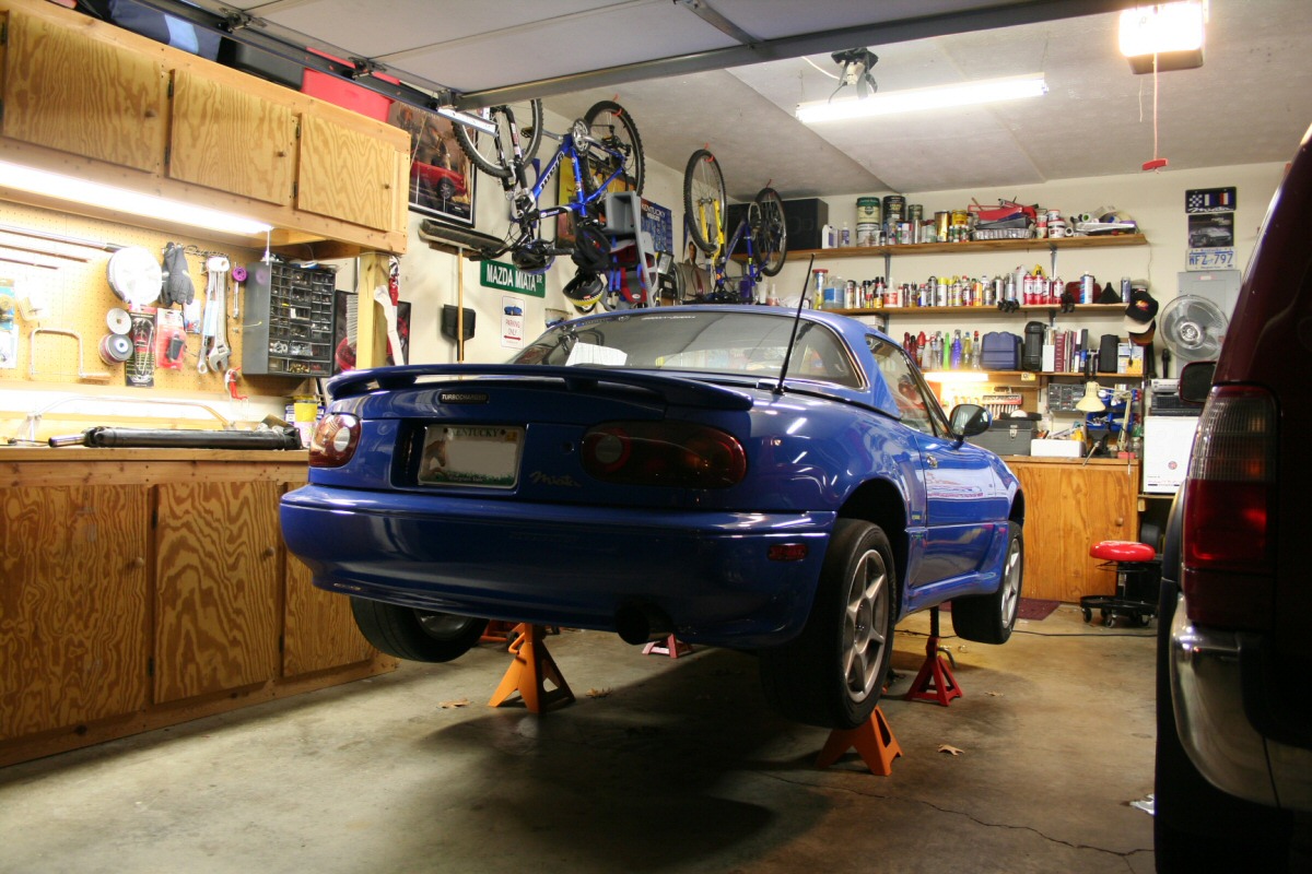
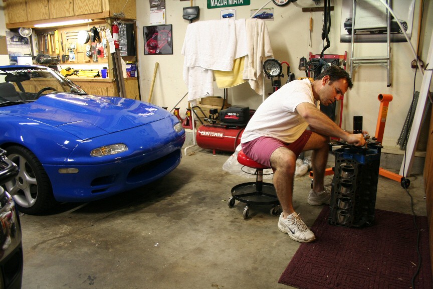
11/26/07 - Well, 2nd gear in the
miata tranny failed so it's time to get serious and start the tear down.
Several parts will be sold to
help fund the V8 project. It has "begun". I am
betting it will be at least a year before completion.
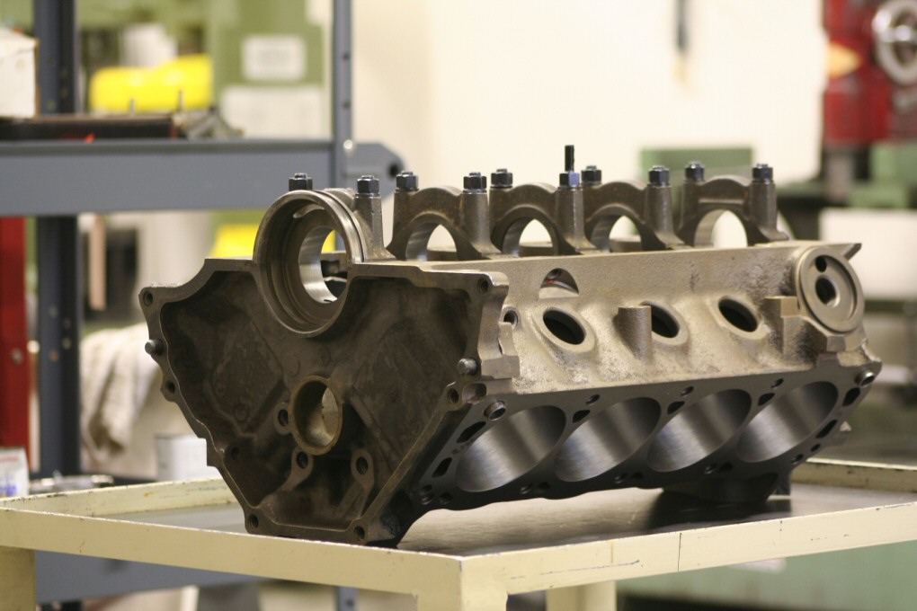
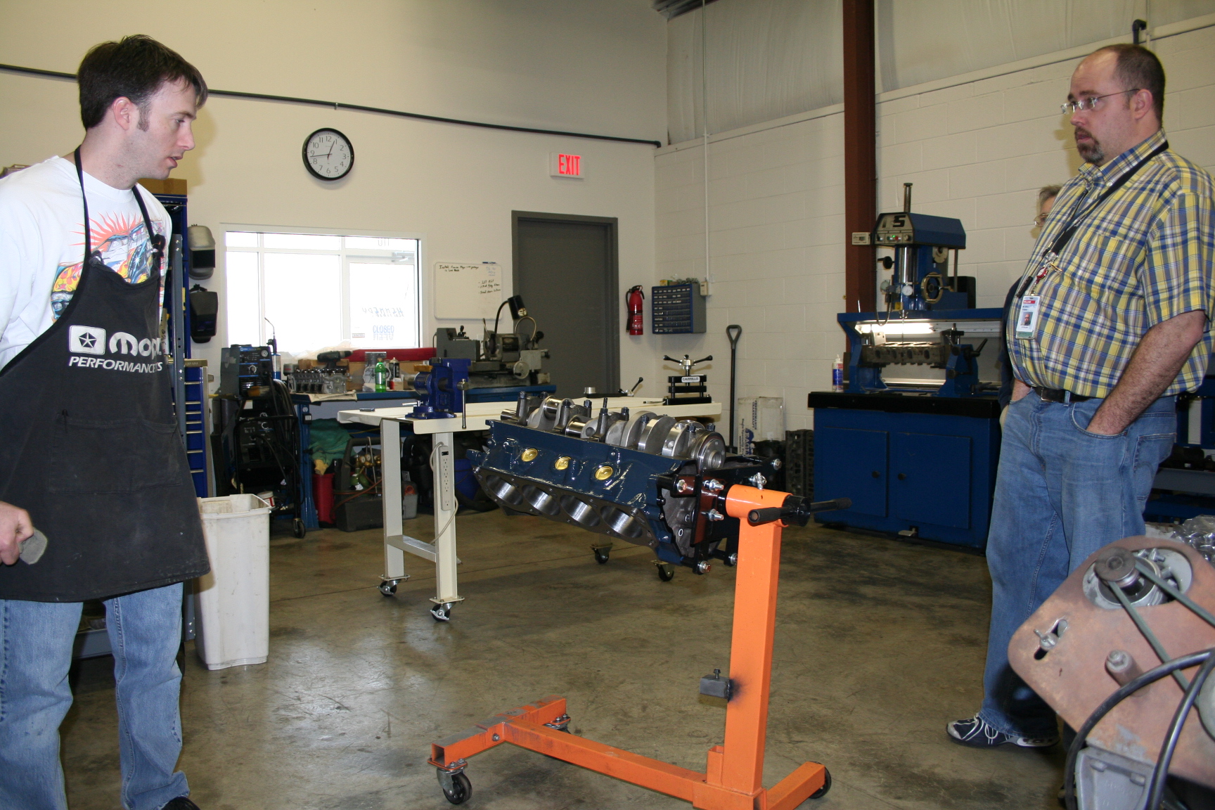
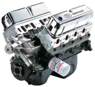
12/5/07 - I purchased a block that
hasn't been modified and have dropped it off at Kennedy Performance to
be cleaned, checked for cracks, square decked, bored/honed 0.030 over,
align
honed, swap oil galley plugs for threaded plugs.
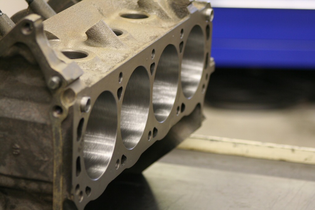
12/14/07 - Block machining work is
done for now. Next step will likely be the rotating assembly
(pistons, rods, crank, flywheel, harmonic balancer). These need to
be balanced then installed. Clearance issues with these parts is a
concern so it's the next step in case additional machining needs to be
done.
12/16/07 - I've been asked a few
times why I'm planning on going with a carburetor instead of electronic
fuel injection. Well, here's why I've decided on going this route:
Cheaper, fewer parts, simpler
Possibly more power
Air filter/intake fits better
into the Simpson cowl hood I already have (which allows for a nice
path to cooler inlet air) and looks kinda cool under the hood
Just to be a little different
I have a thing for
'60's muscle cars.
and I've just got this itch of
wanting to do a carb'd setup that I can't seem to shake.
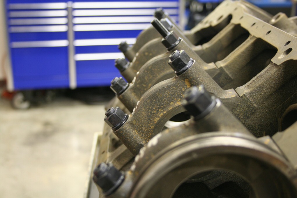
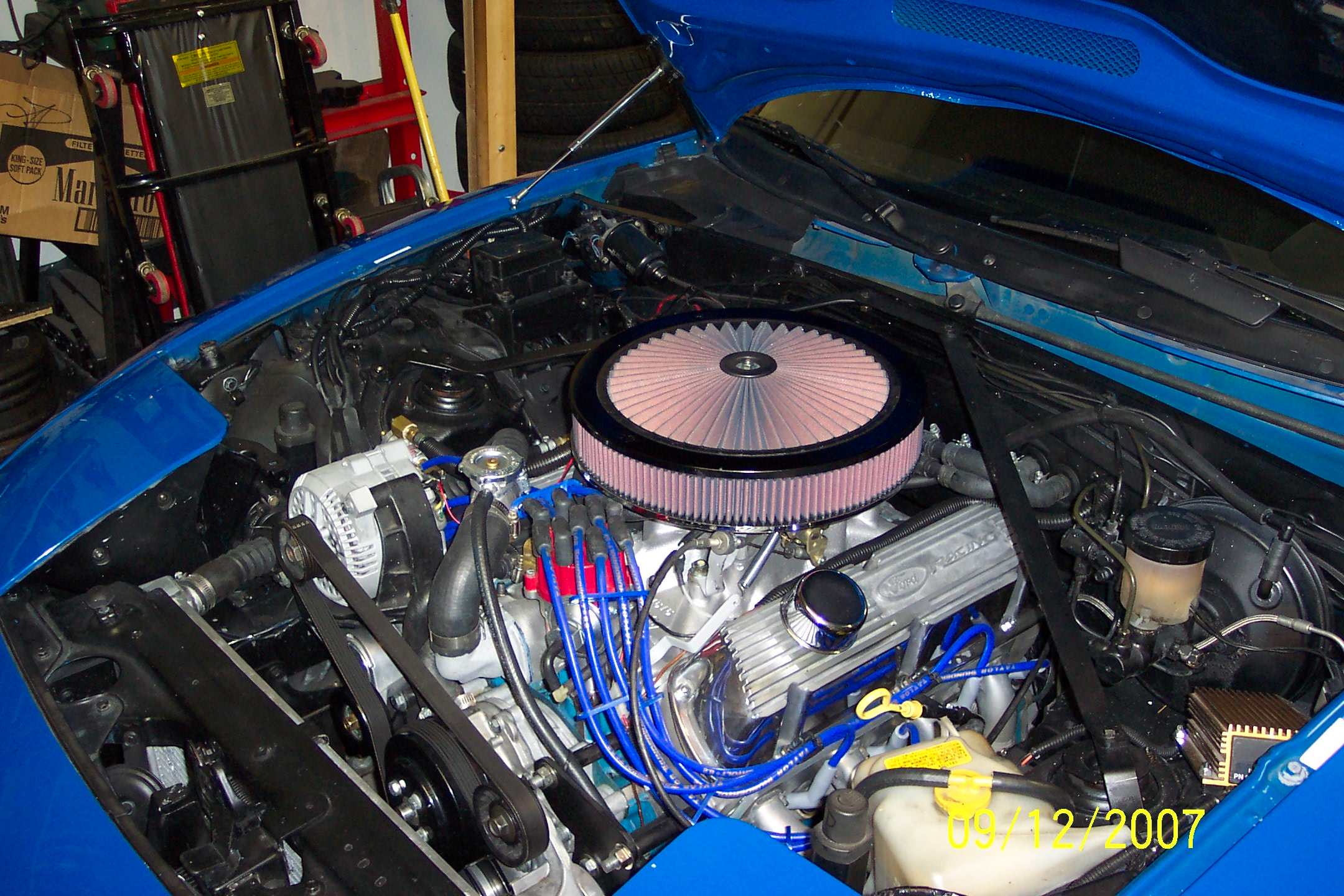
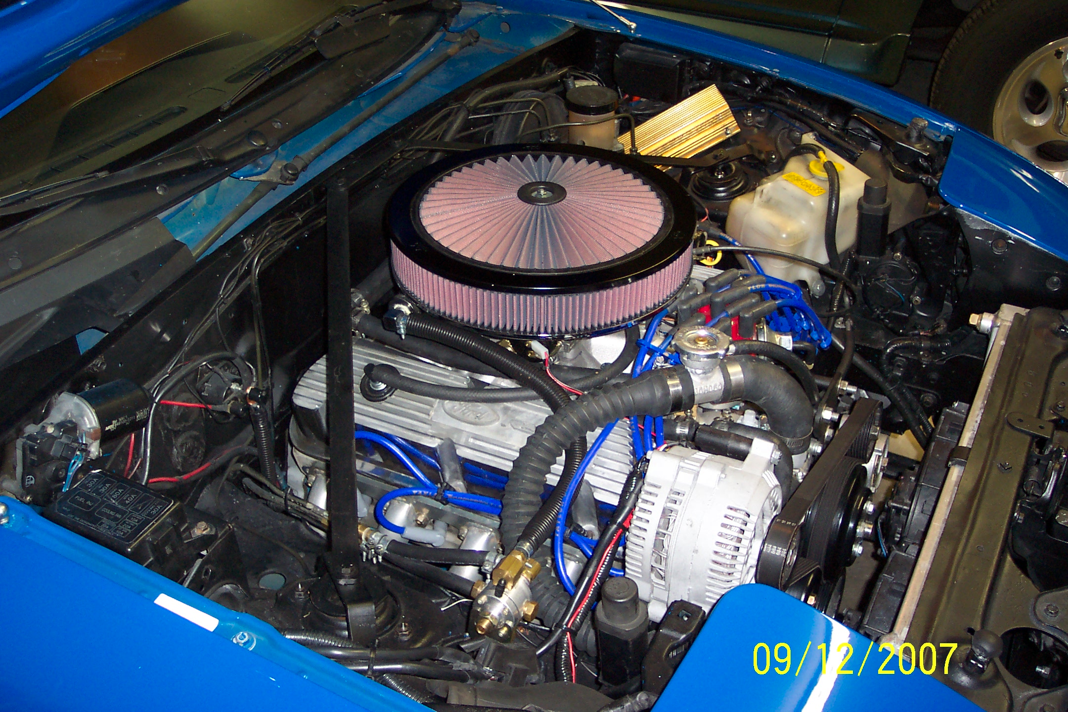
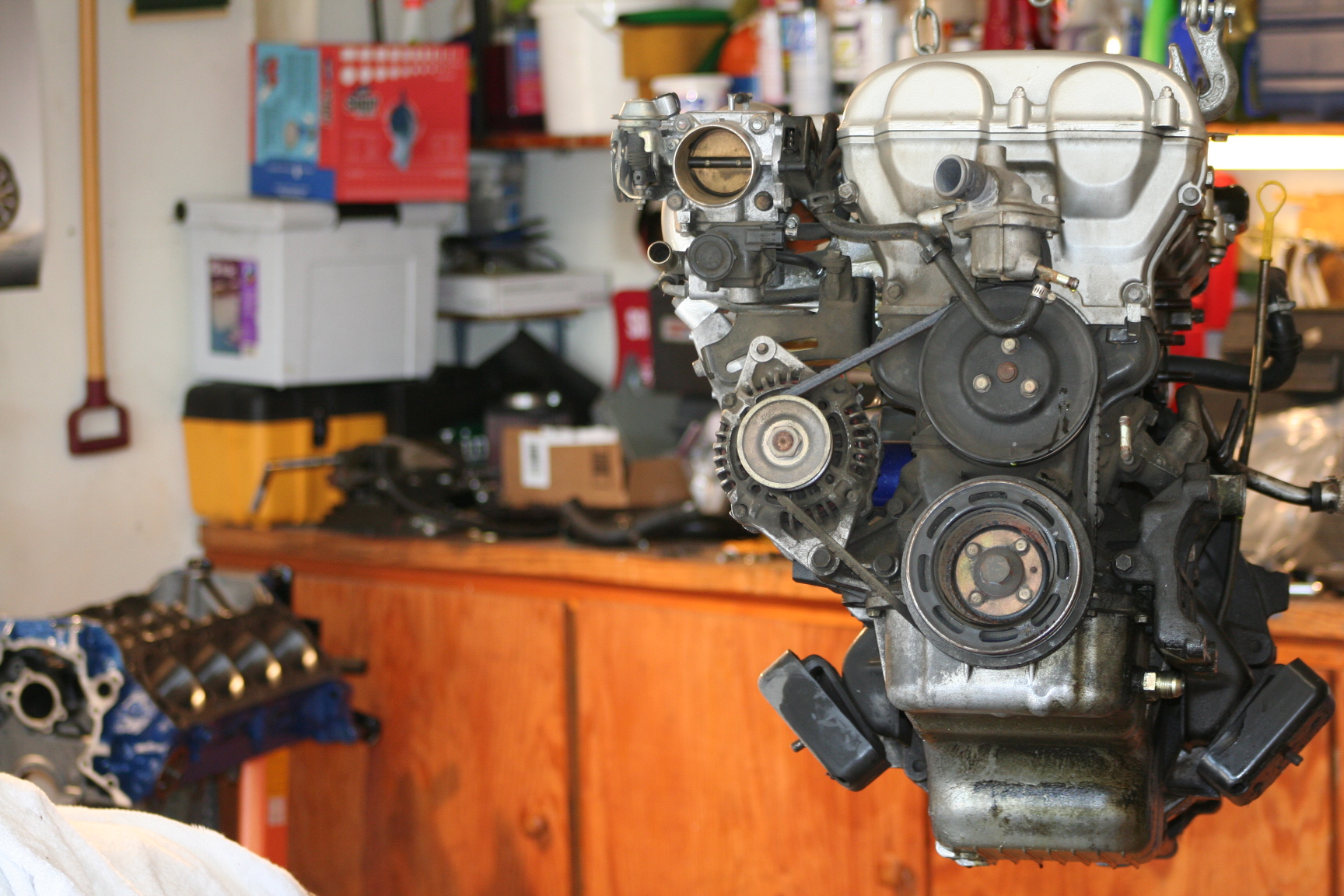
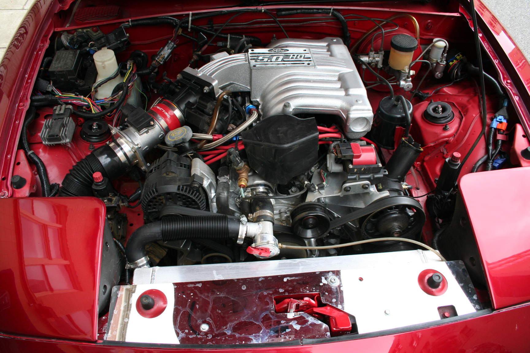
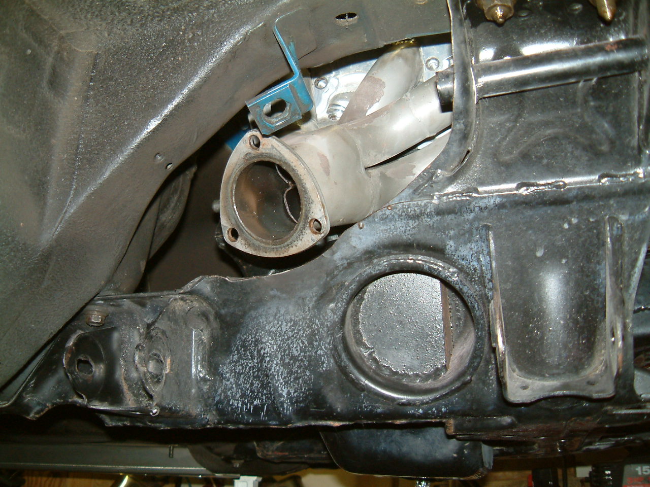
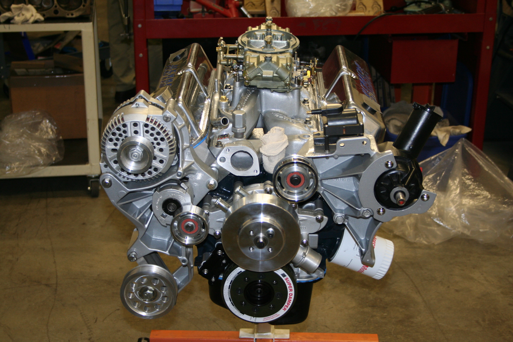
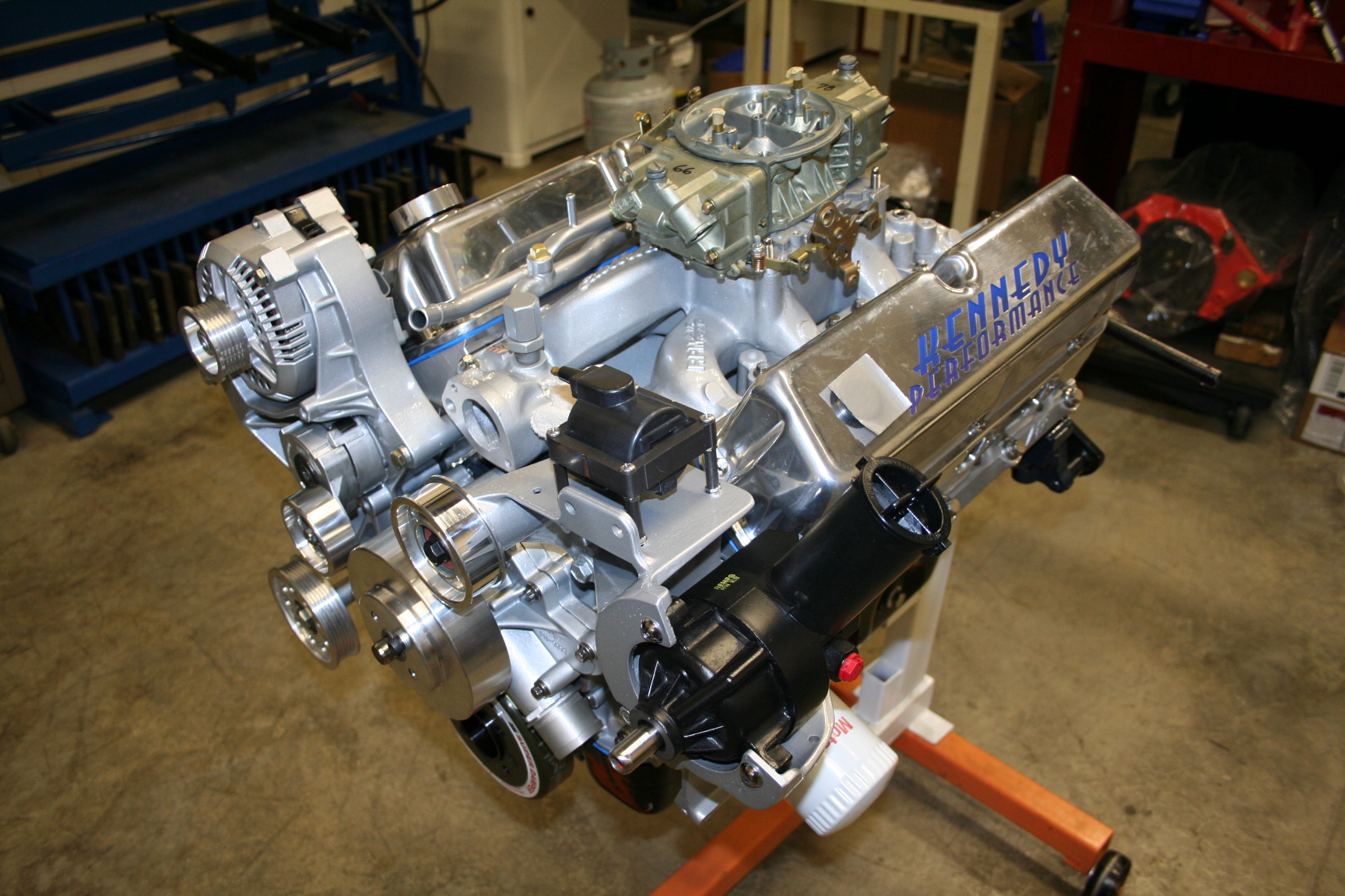
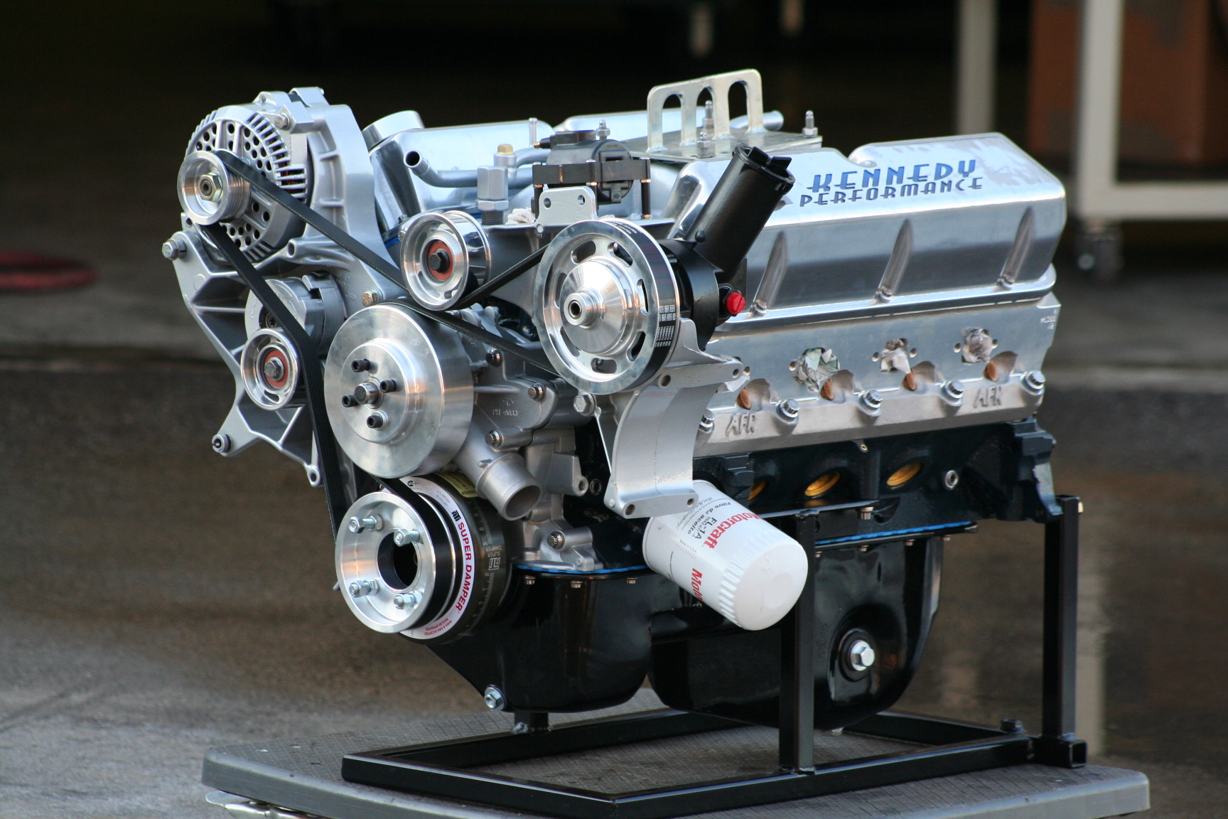
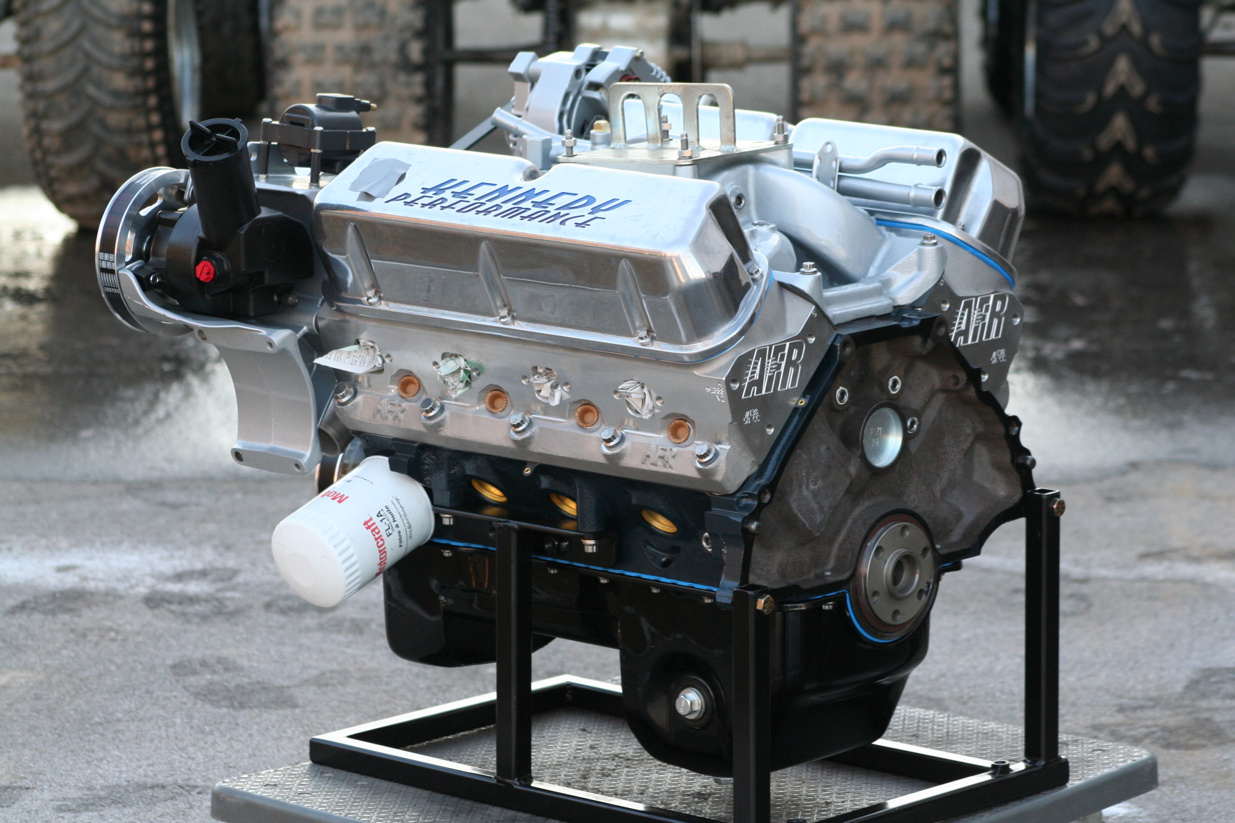
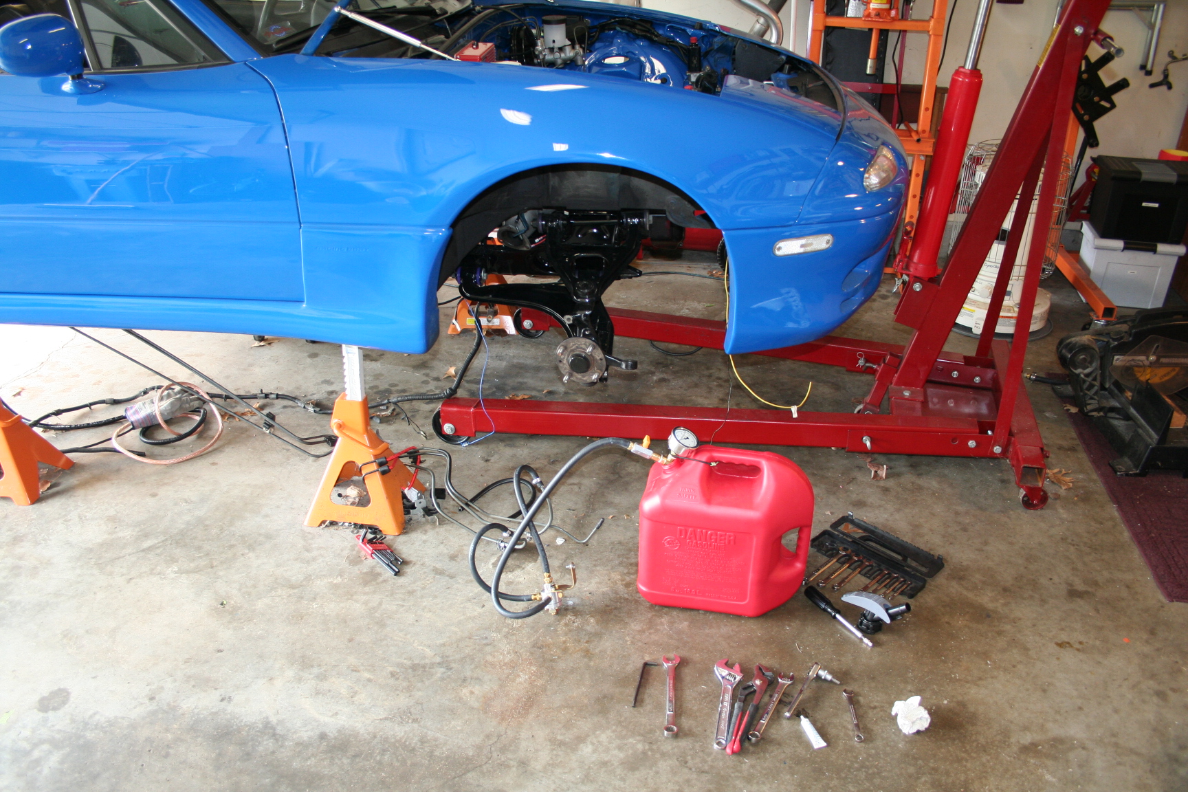
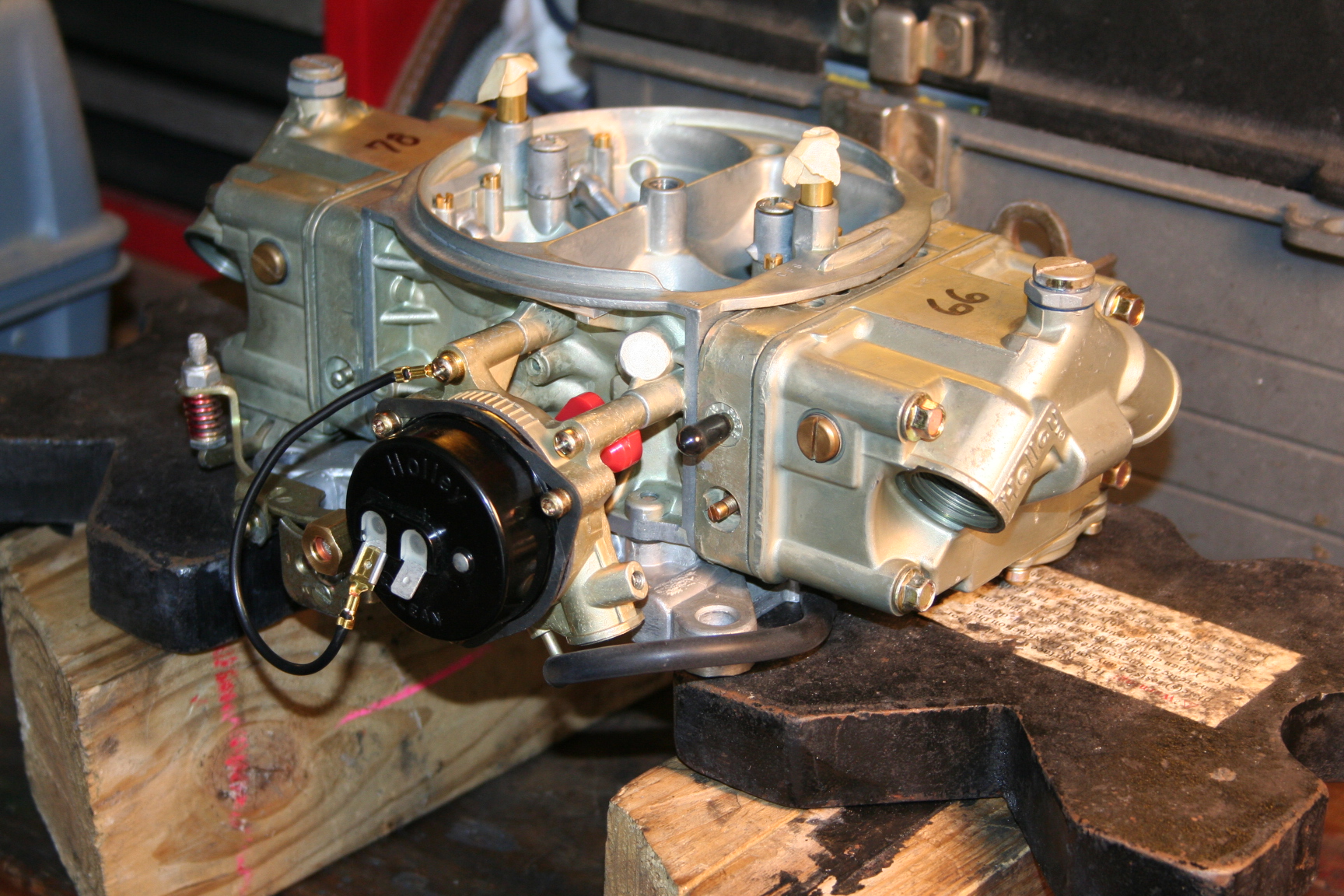
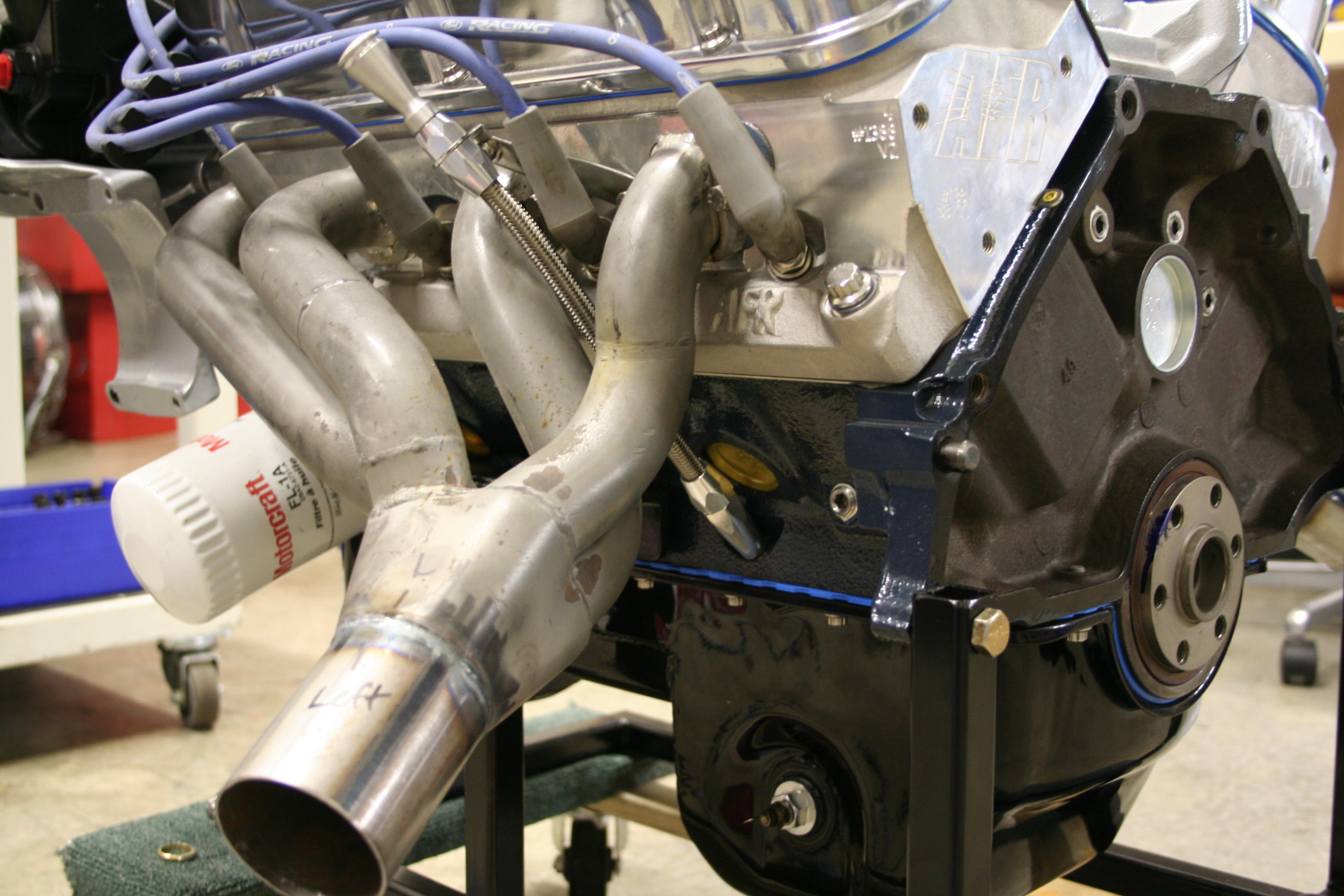
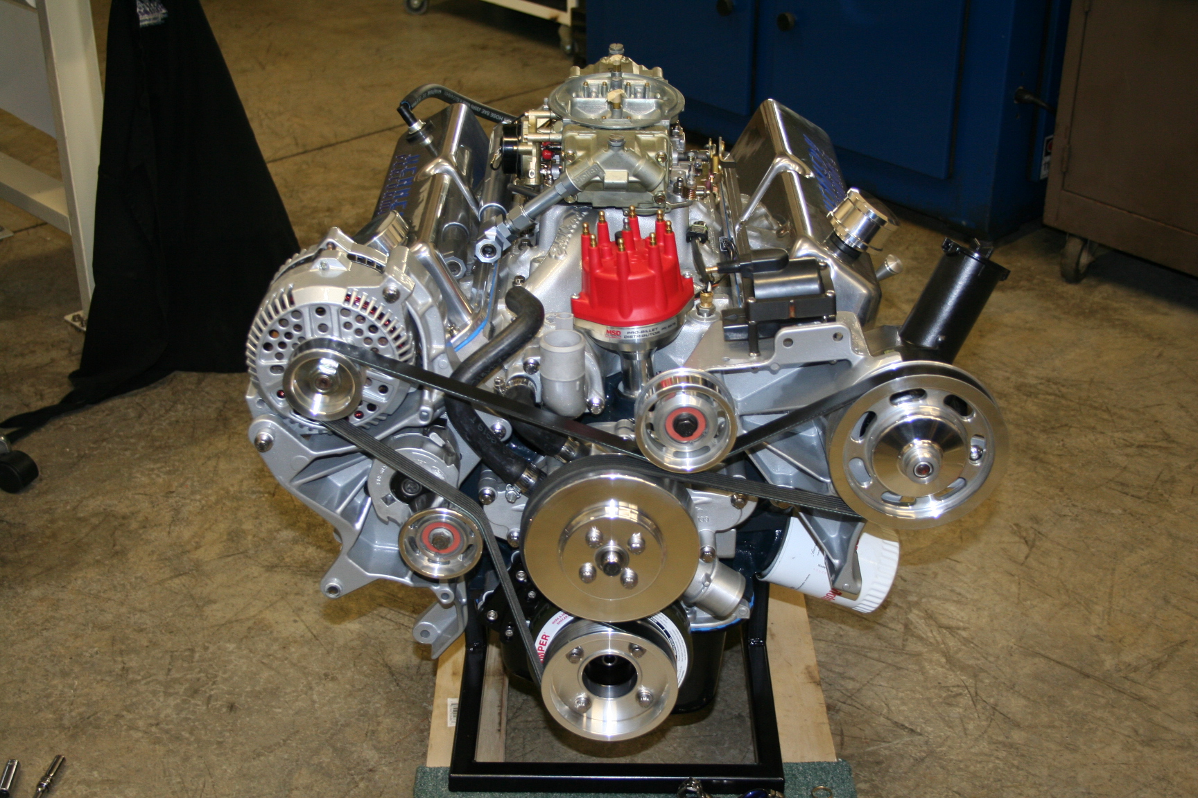
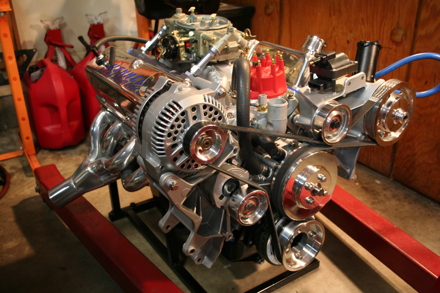
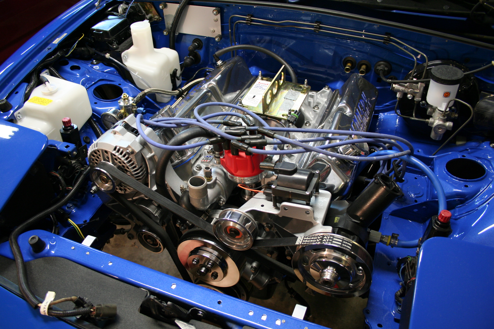
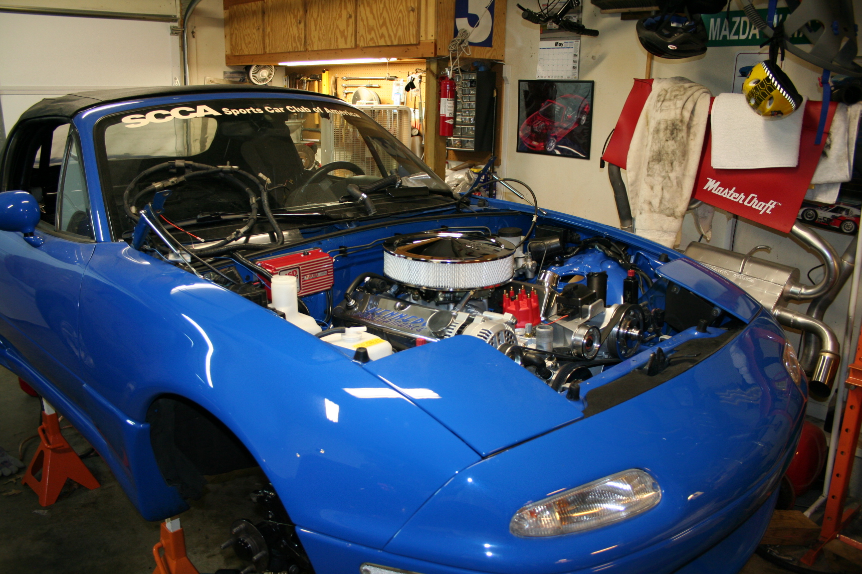
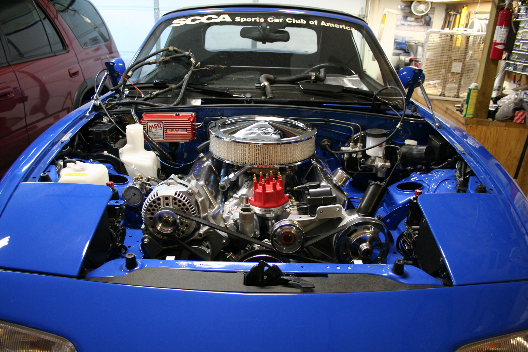
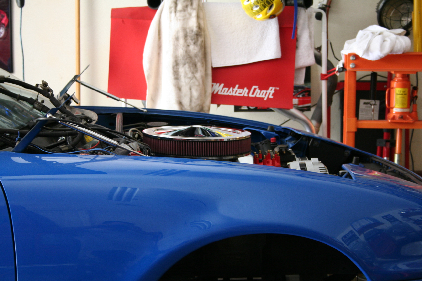
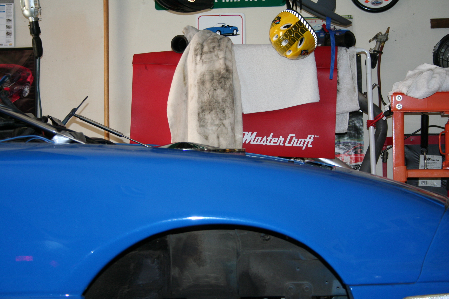
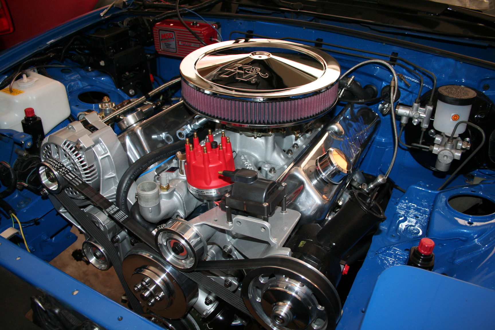
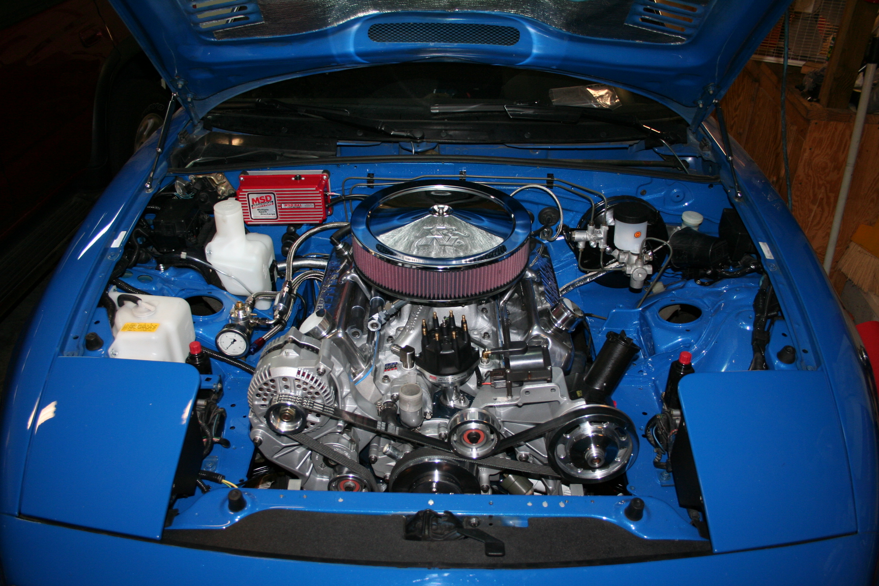
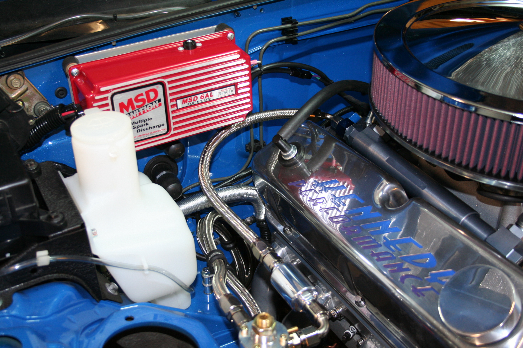
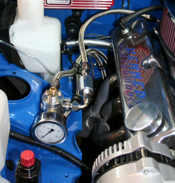
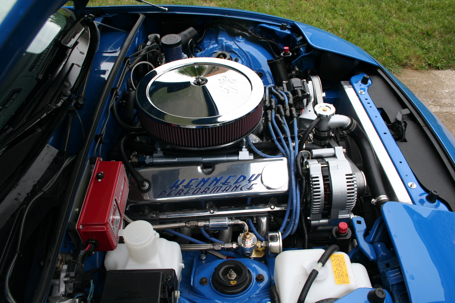
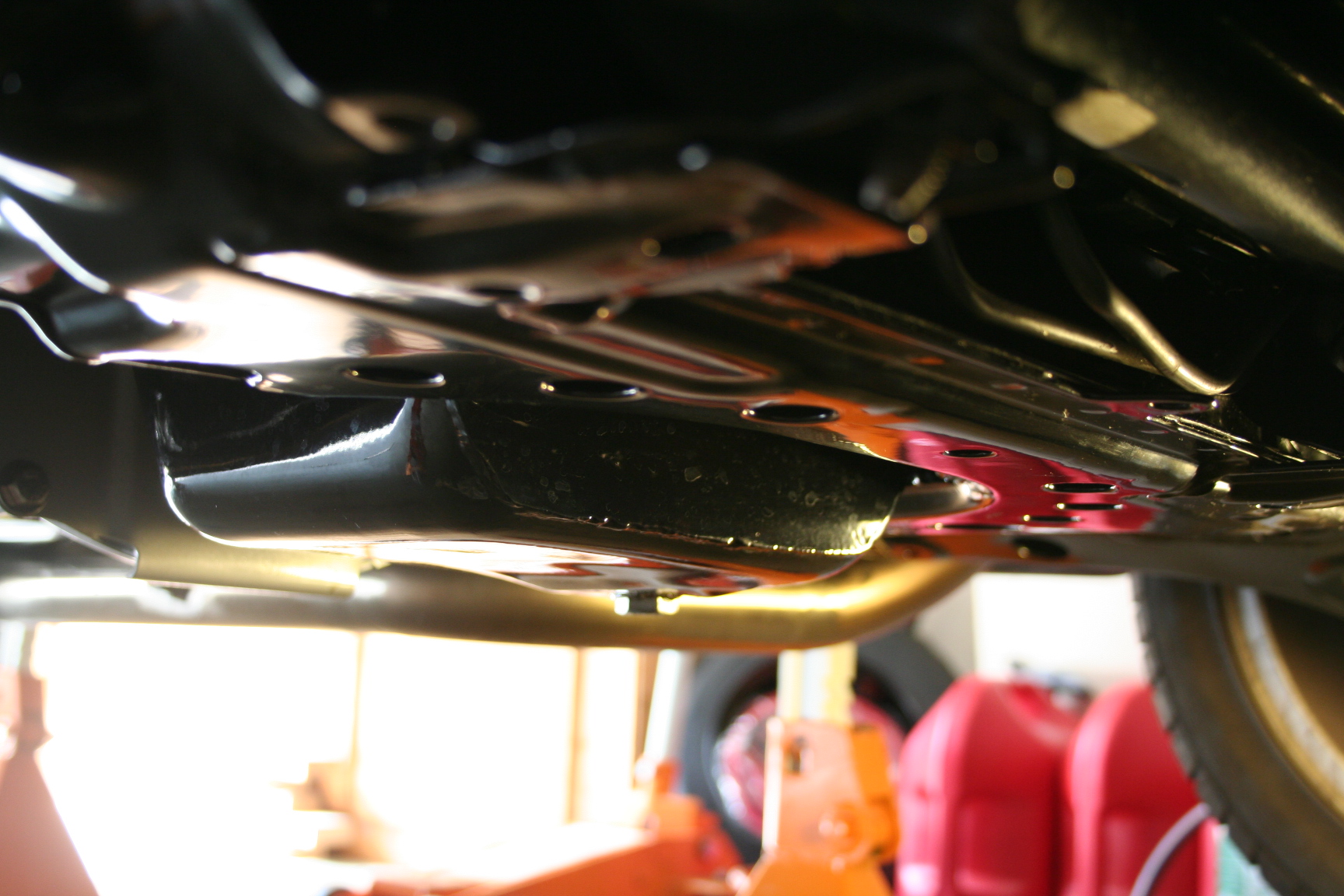
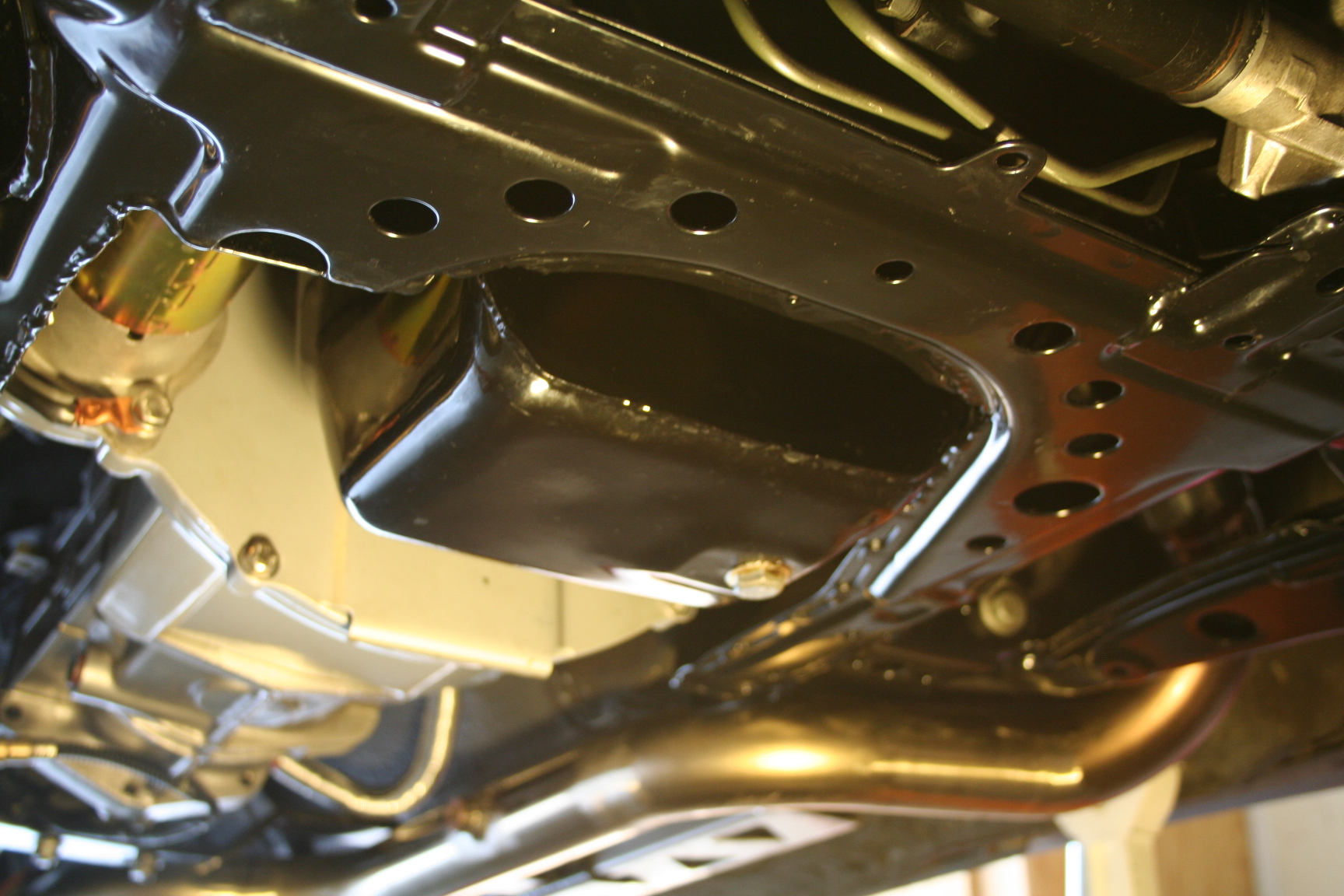
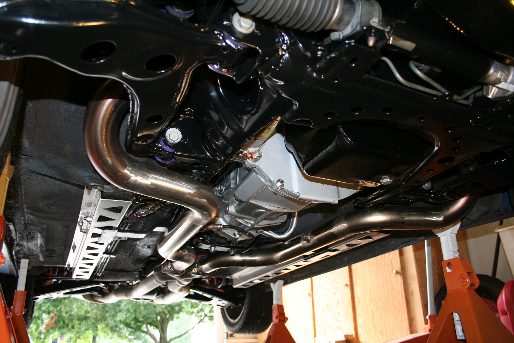
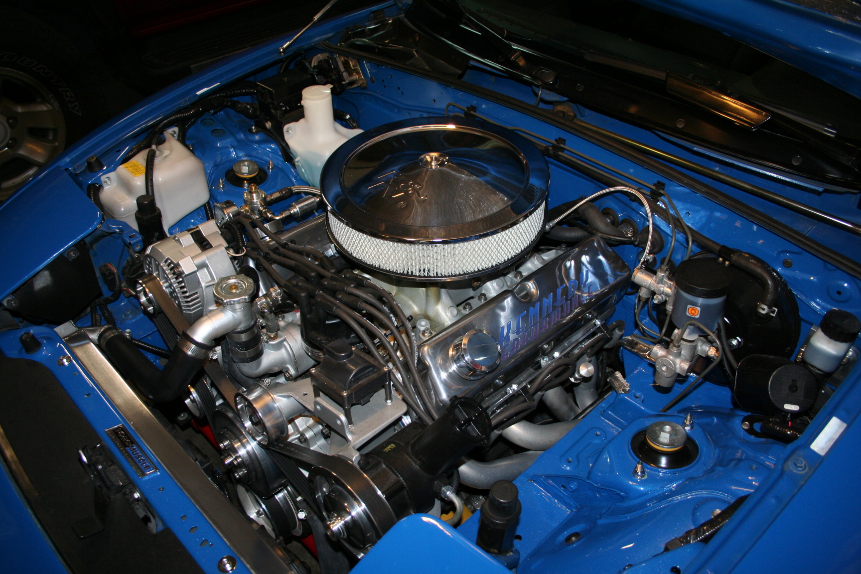
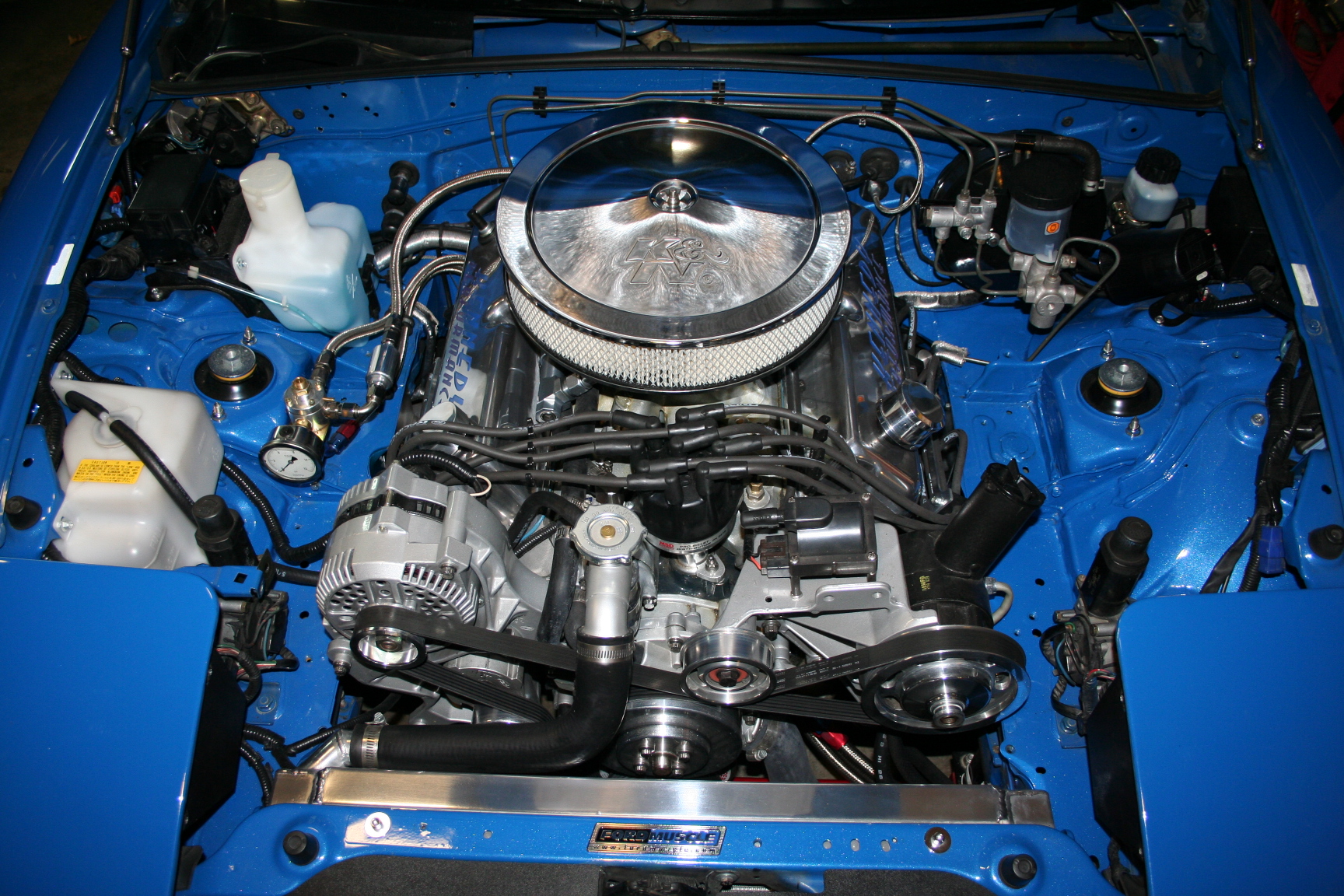
Here are some pics of a friend's
V8 miata. It's a carbureted 347 stroker. Lots of things to
look at and learn.
I may look back and think it's a
crazy idea, but for now it seems that a well running, streetable, carb'd engine is possible. Although it is older technology, I
should have the benefits of a refined design by using the most recent
offerings from Holley (or maybe Edelbrock).
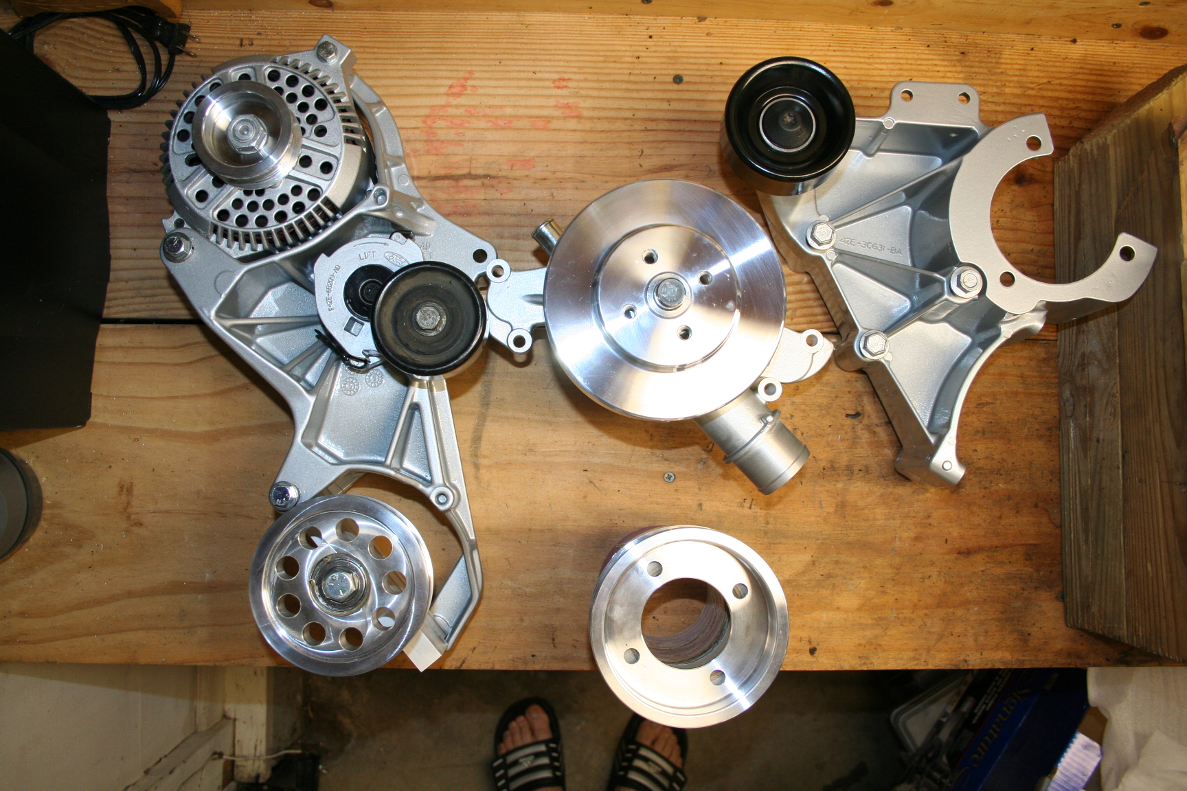
12/18/07 - I purchased a 94-95
Mustang timing chain cover and am searching for the 94-95 engine
accessory brackets (alternator/tensioner pulley/smog pump deletion
pulley bracket and power steering/idler pulley/air conditioning
compressor bracket). Also needed: 94-95 water pump, 94-95 WP
pulley, and 94-95 crankshaft pulley. I think there is also a
crankshaft pulley spacer that is unique, as well as the harmonic
balancer.
2/01/08 - I now have the 94-95
Mustang GT accessory brackets with new idler pulleys, used tensioner,
new water pump, new WP pulley, used alternator, used bell housing and
alignment plate. I also went ahead and ordered the modified oil
pan from Monster Miata so that clearances can be verified with the rod
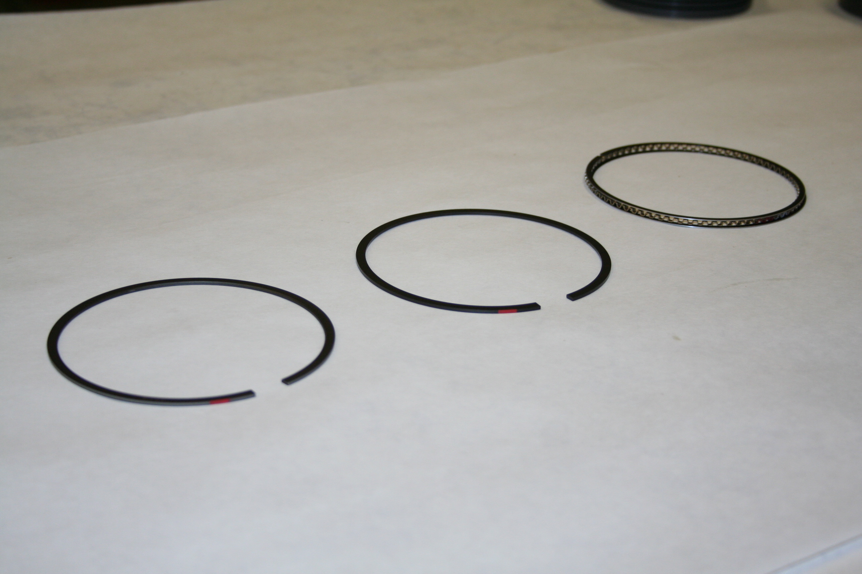
cap bolts/nuts. Pistons, rods, crank, rings, flywheel and
harmonic damper will be ordered soon.
2/03/08
- The miata engine and transmission, along with the turbo and other
parts have been removed and are up for sale.
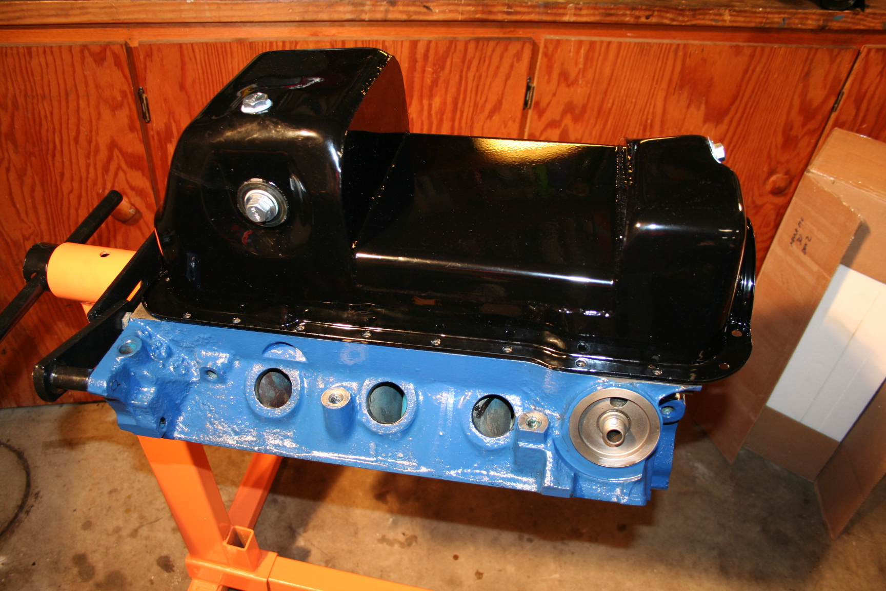
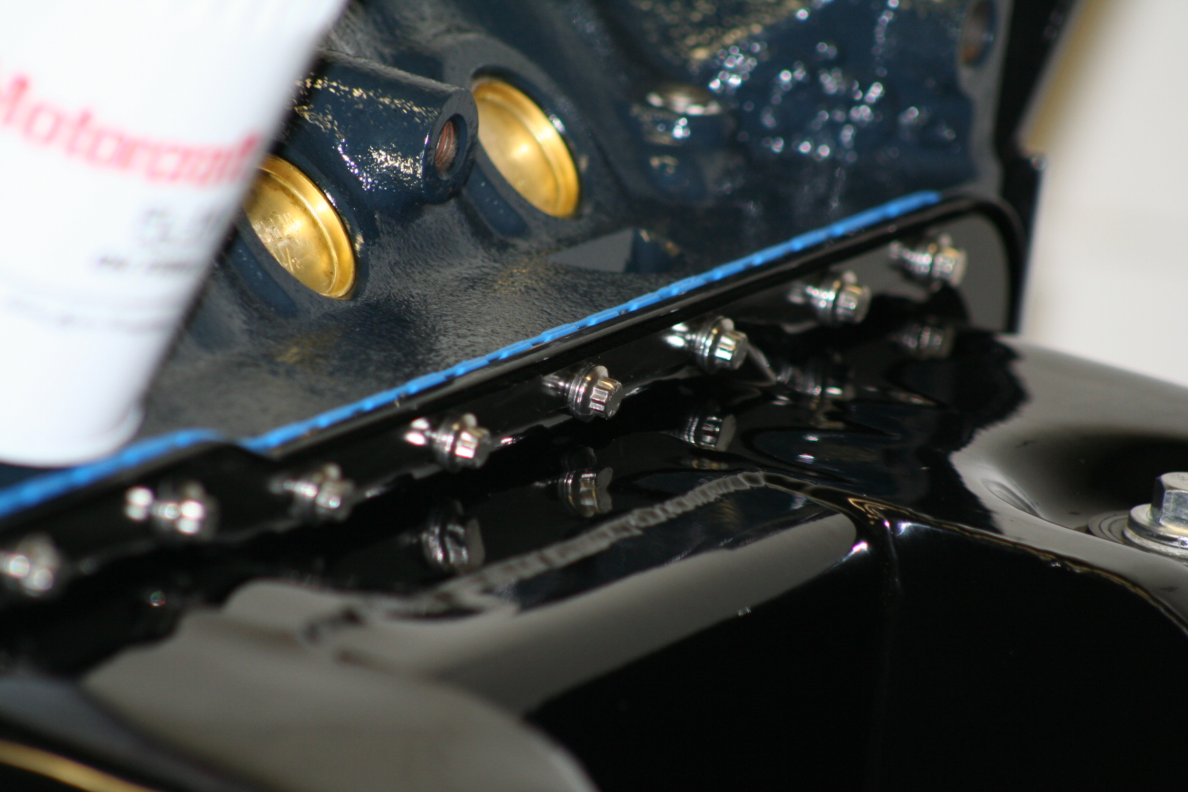
2/08/08
- The oil pan from Monster Miata came in. Looks nice! Here
it is sitting on my spare block.
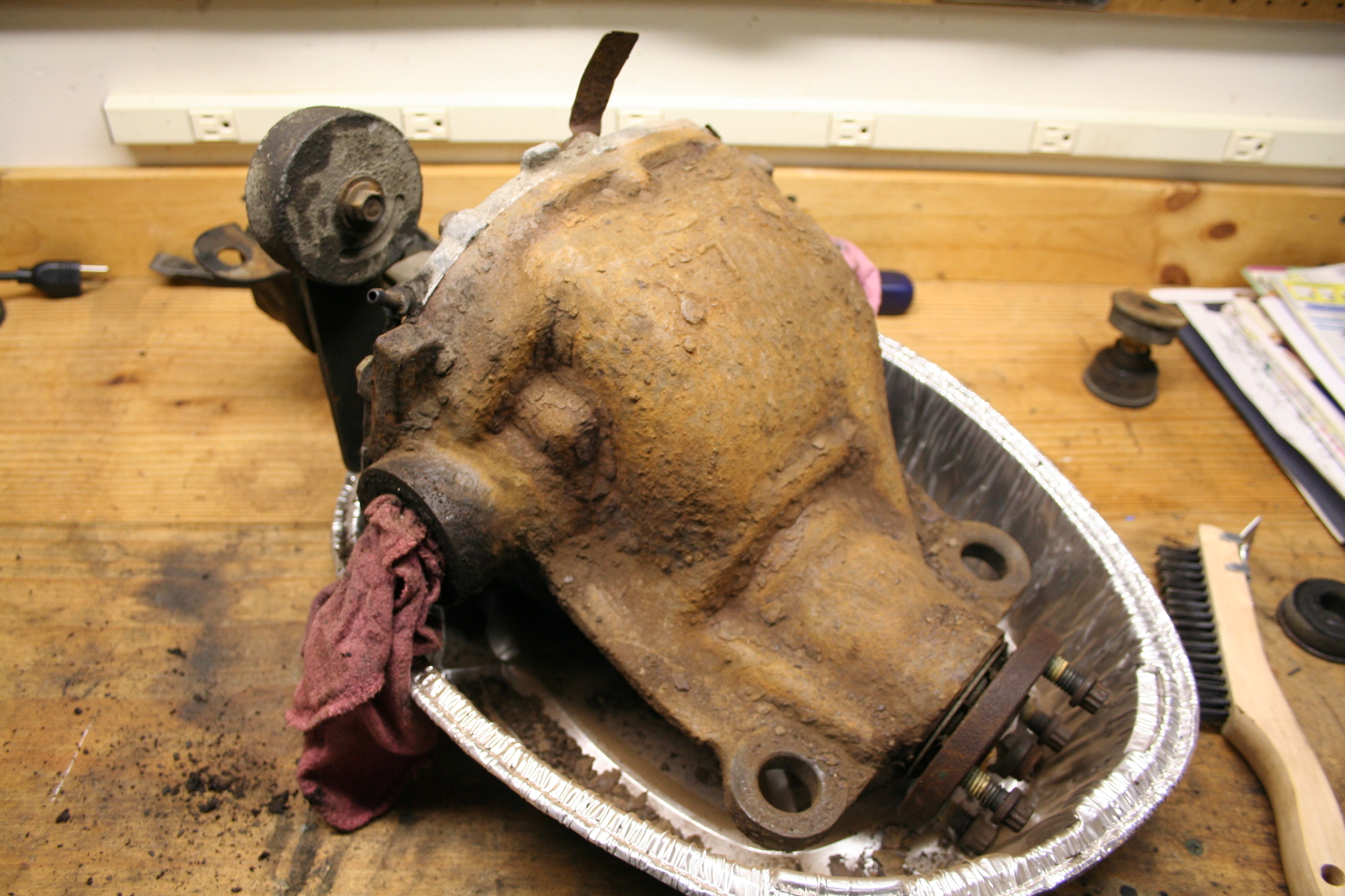
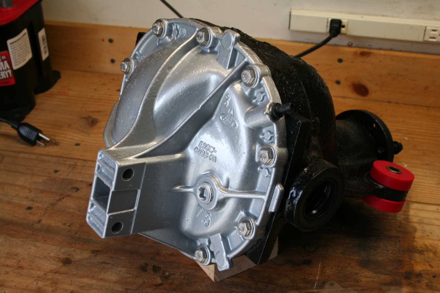
2/11/08
- I picked up a '93 Thunderbird diff today. It's just an open
diff, no LSD but I'll plan on adding that when it gets torn down.
This one had a little leak and is a bit nasty. Time for the wire
brush.
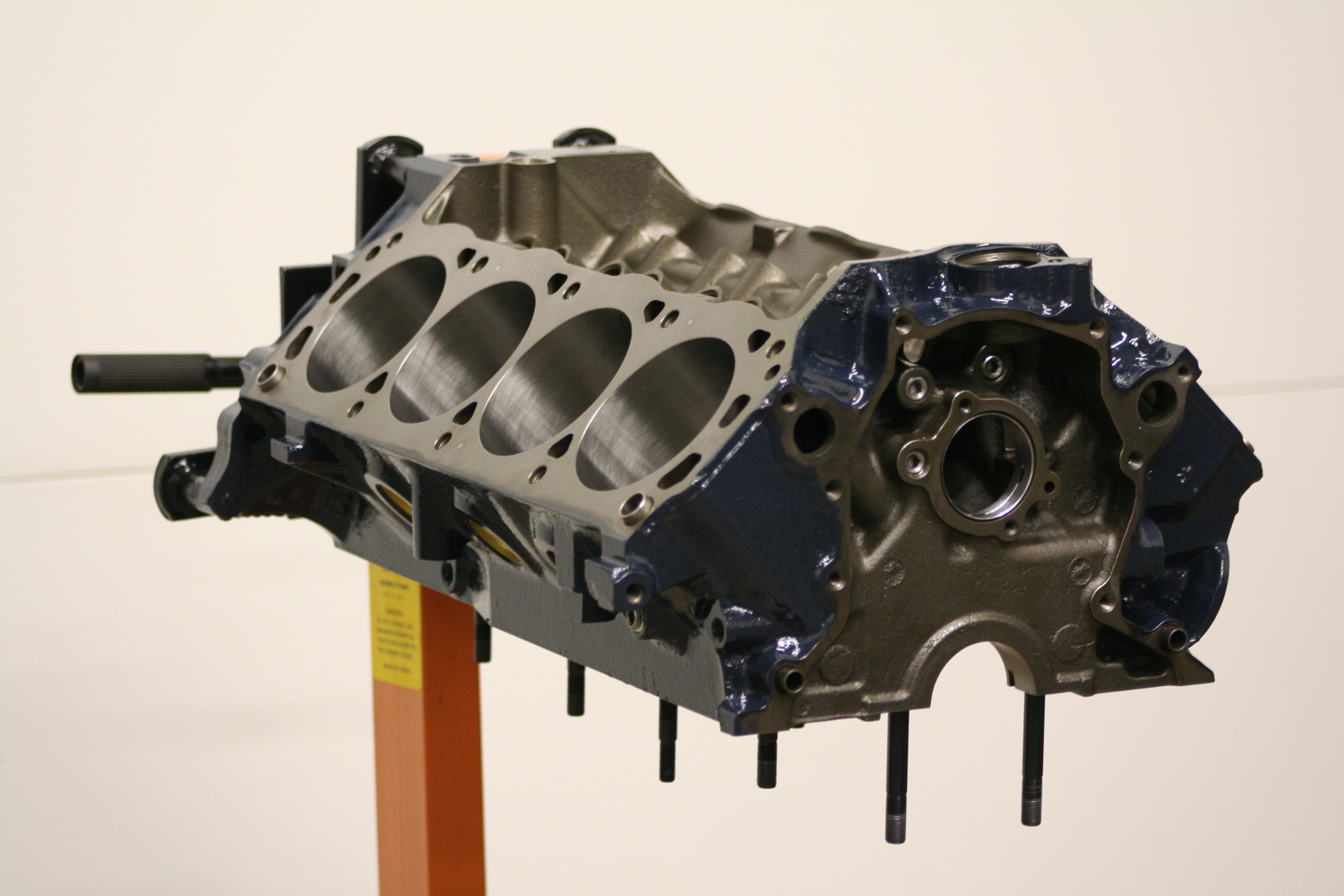
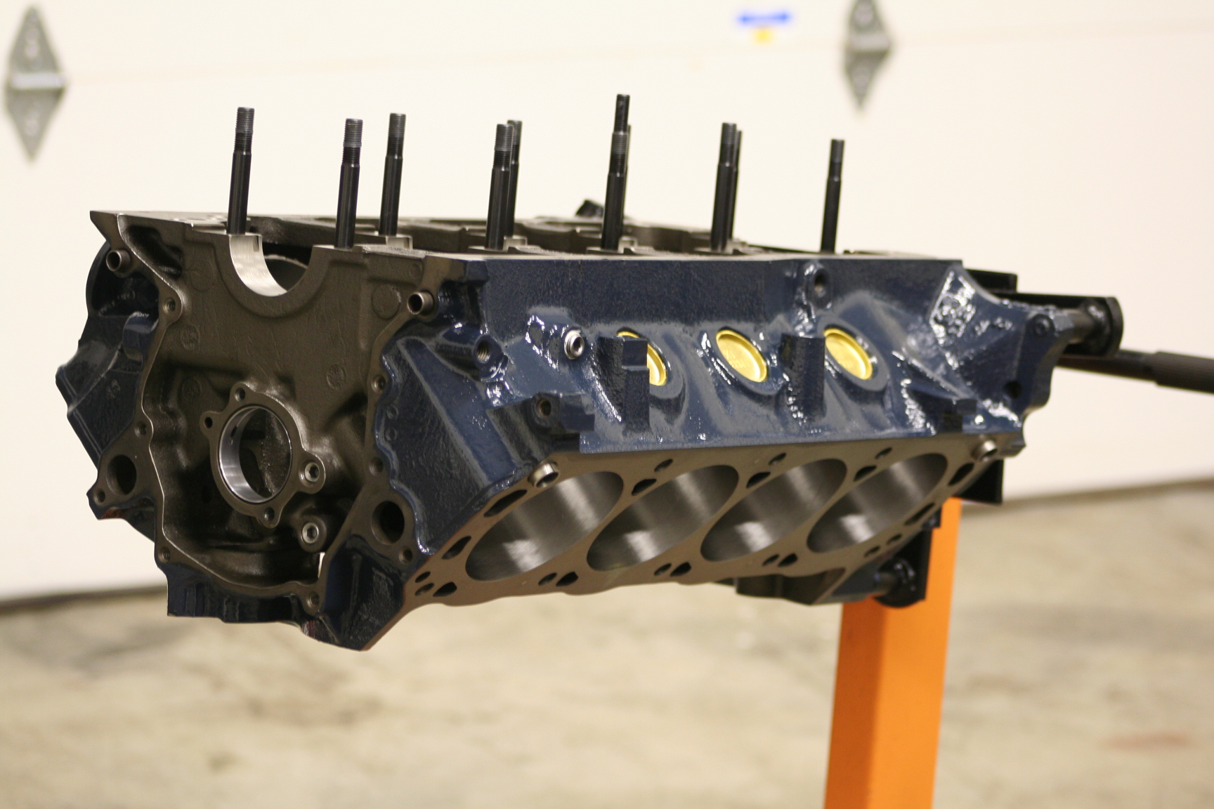
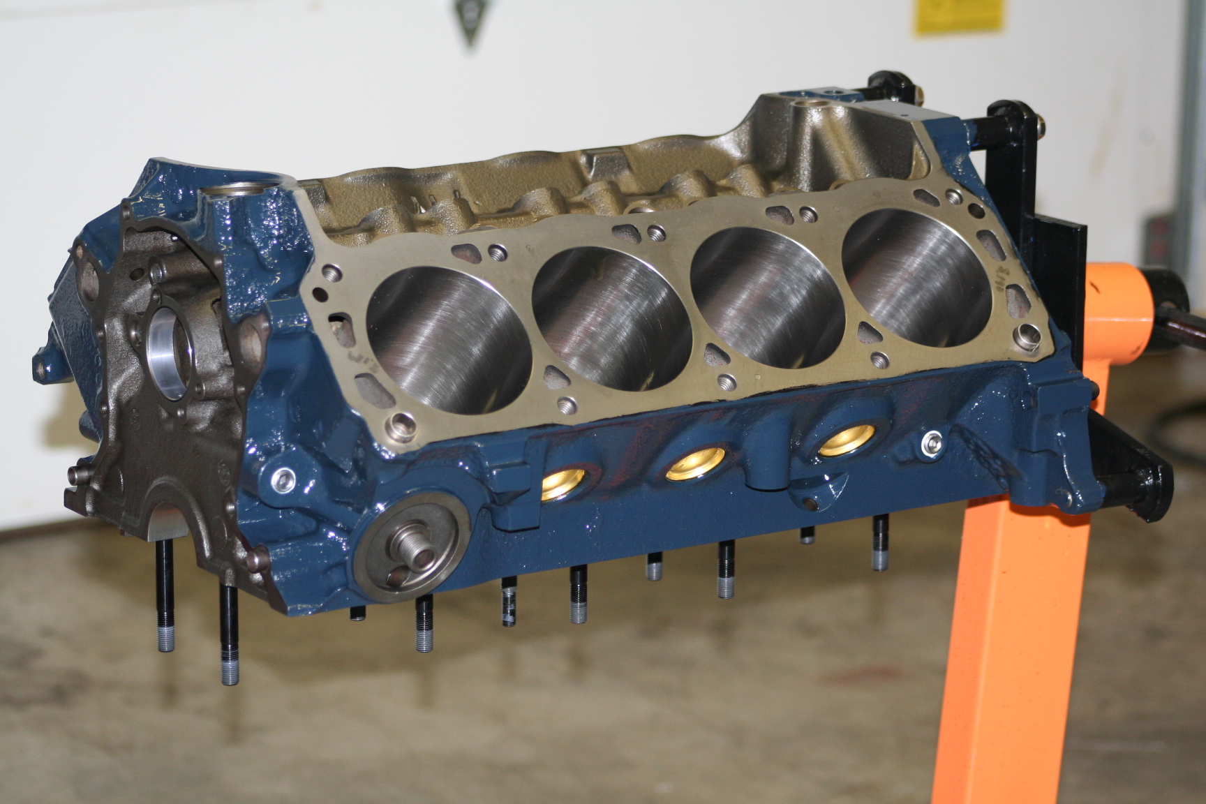
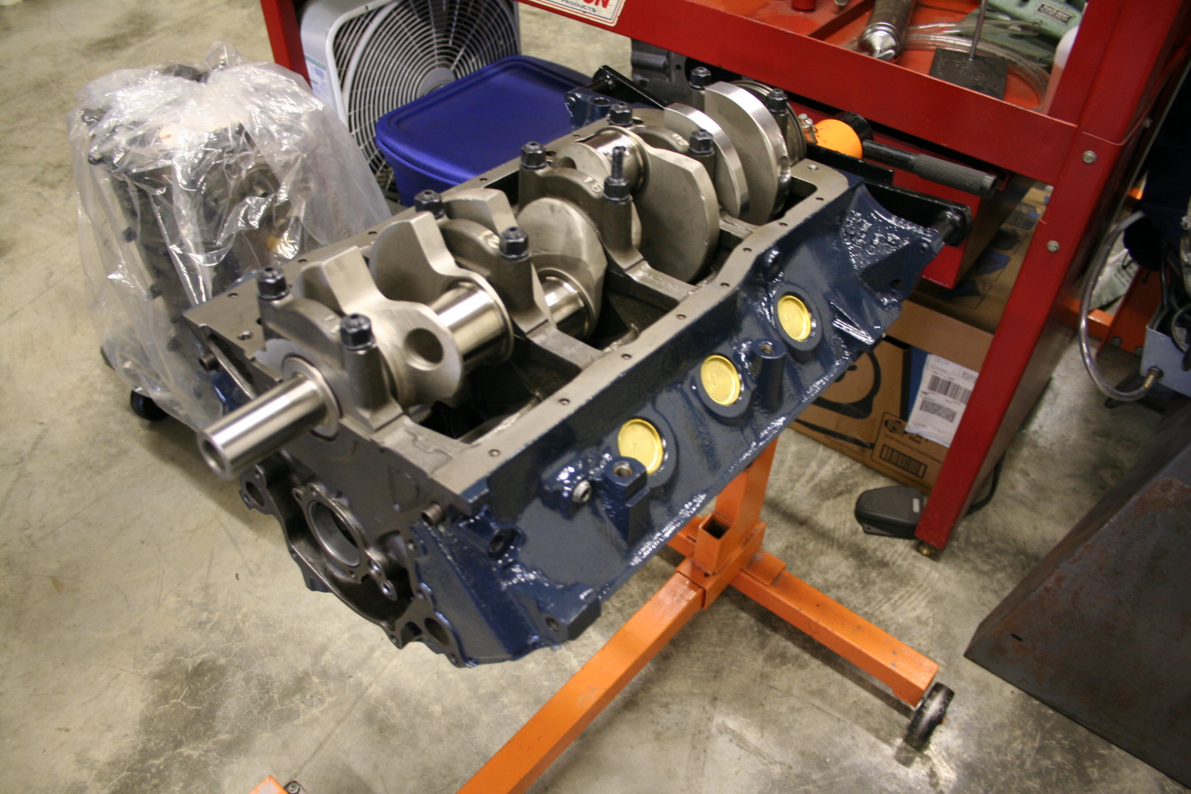
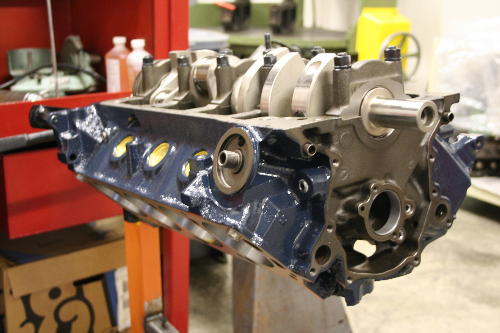
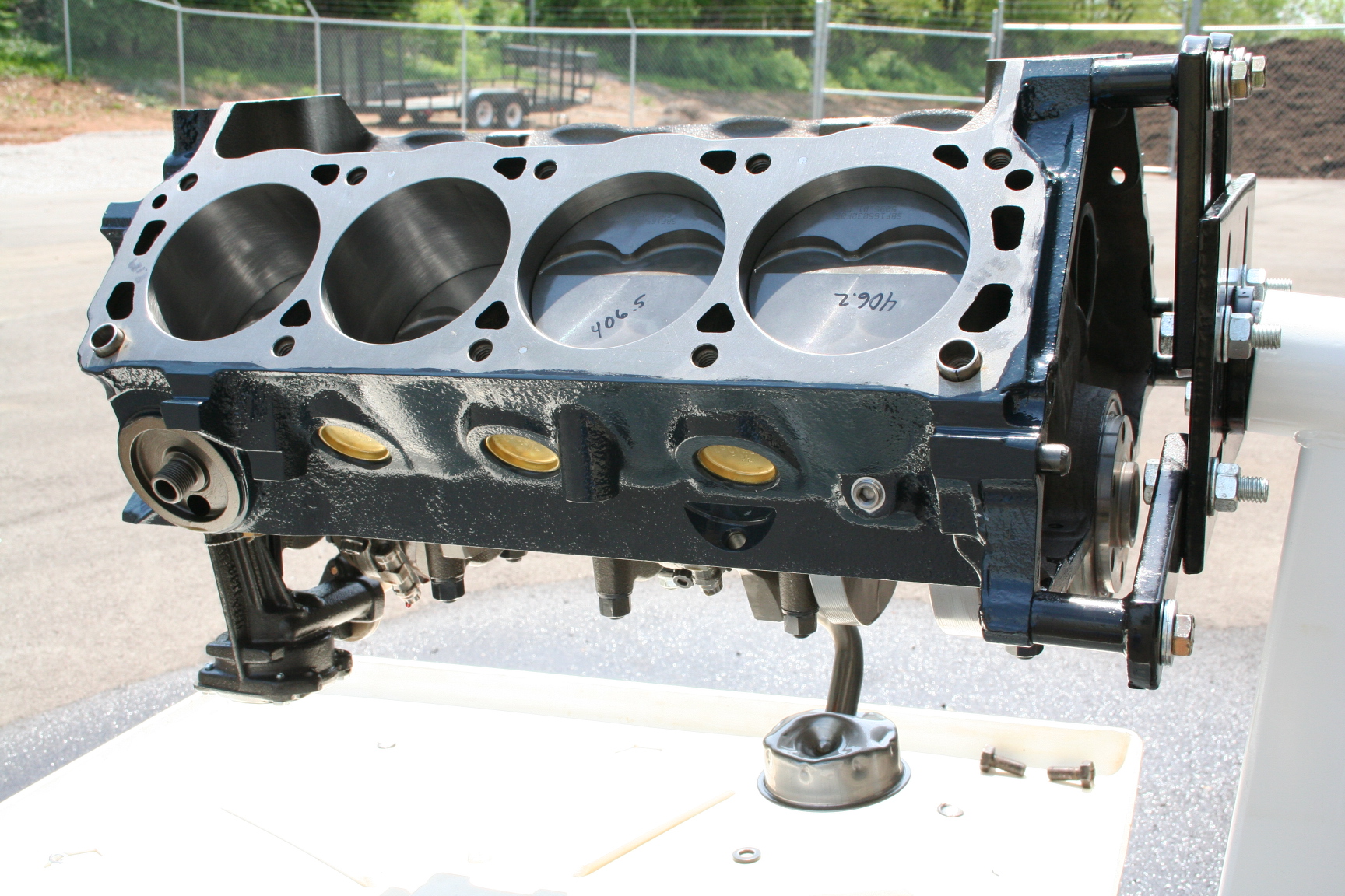
2/29/08
- I brought my block home from the machine shop today to give it a coat
of paint. I used POR-15 Paint-Over-Rust as a primer and POR-15
Engine Enamel as a top coat (painted on as the primer was just about
dry). Here is a shot of it back at the machine shop after a few
days of curing. The color I chose is Ford Medium Blue which is a
bit darker than the Ford Corporate Blue I painted on my spare block.
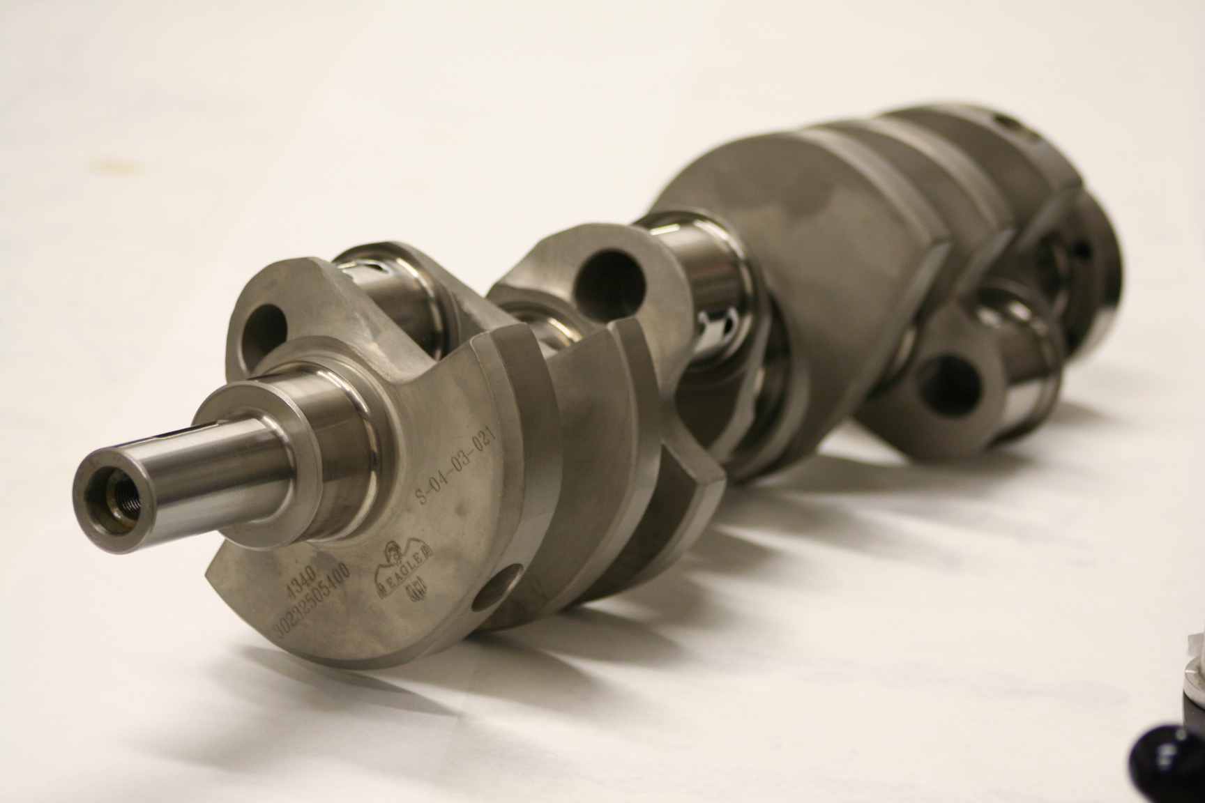
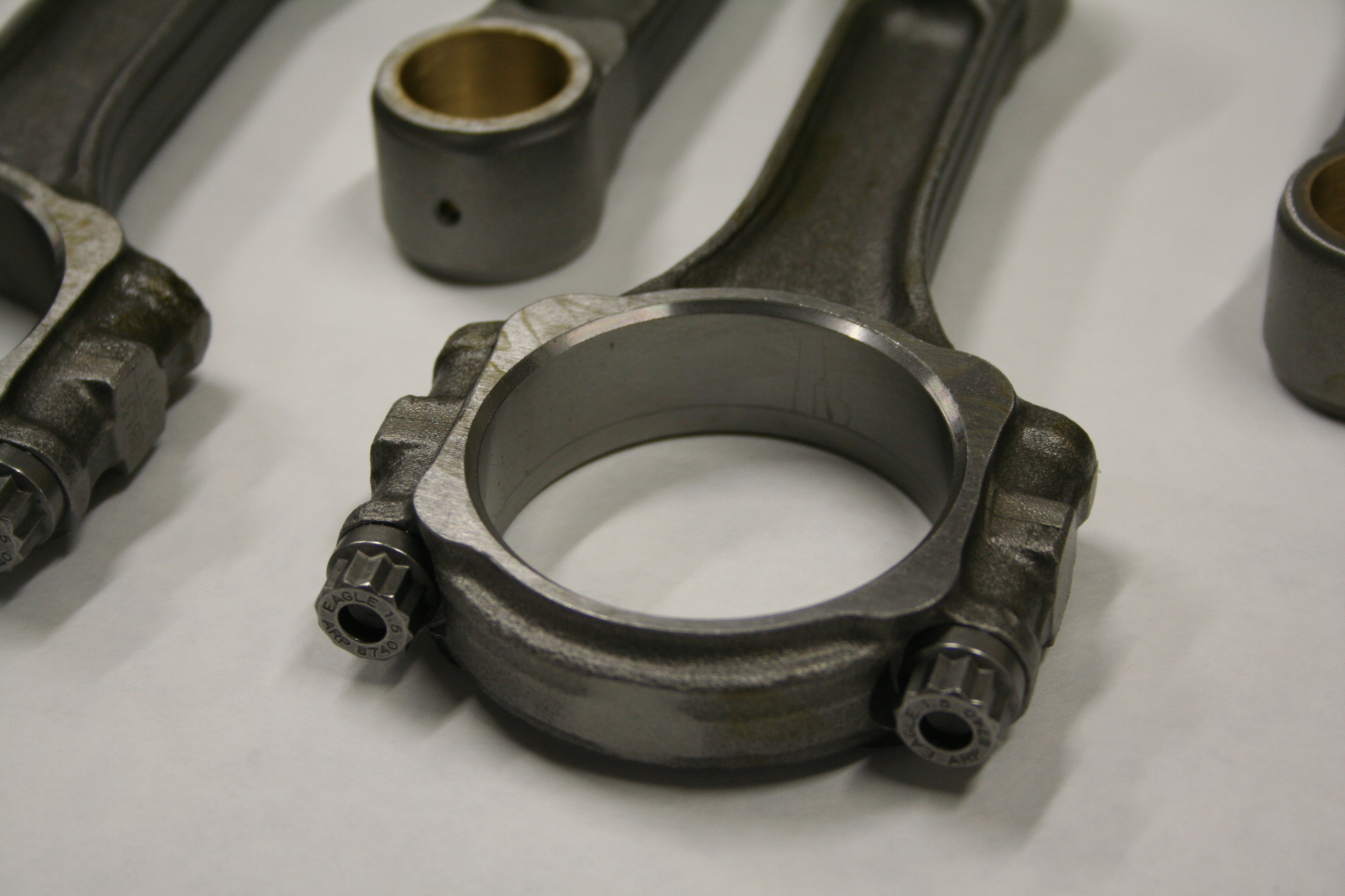
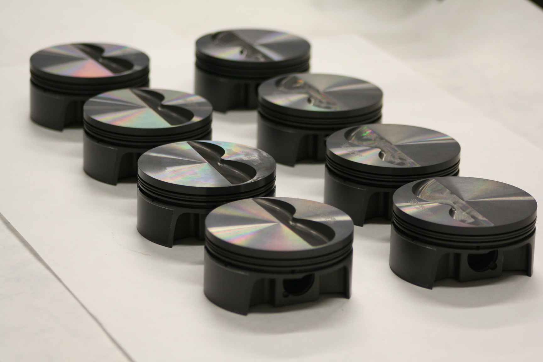
3/04/08 - The crankshaft, rods and
pistons have arrived. I decided on a 331 cid stroker setup instead
of a stock stroked 302 (or 306). I could have gone as far as a 347
stroker but decided to go with the 331 to try to avoid some concerns I
have with the reliability of a 347. Perhaps I'm a little paranoid,
but the 331 seemed like a good compromise with increasing displacement
(power), bringing the usable power/torque curve a little lower in the
rpm range (which means I don't have to rev it as high, which is good for
reliability), and less side loading of the pistons against the cylinder
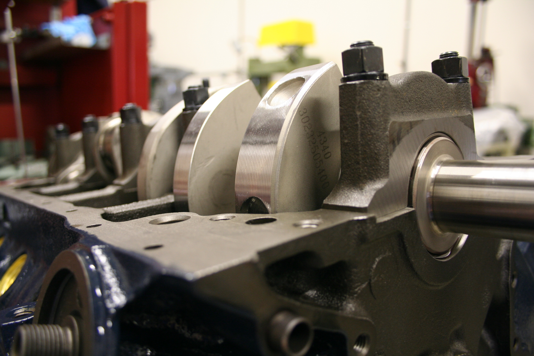
walls. I wanted to go with an internal balance
setup and so I had to spurge for a forged Eagle crankshaft since the
cast ones by Scat and Eagle are not internal balanced. The forged crank
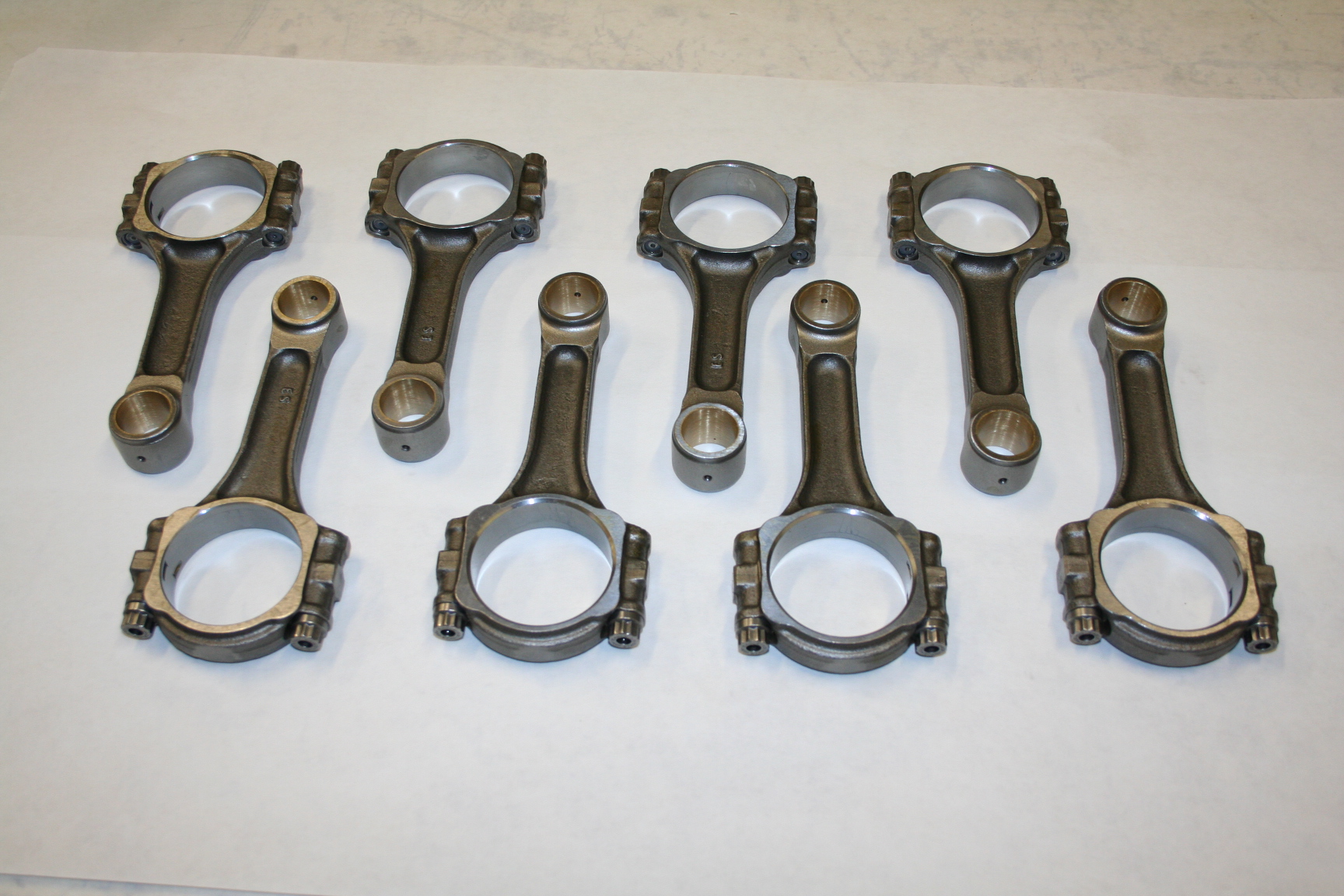
is overkill for my power objectives, but that's ok. I went
with Eagle forged I-beam rods. They will be strong enough for my
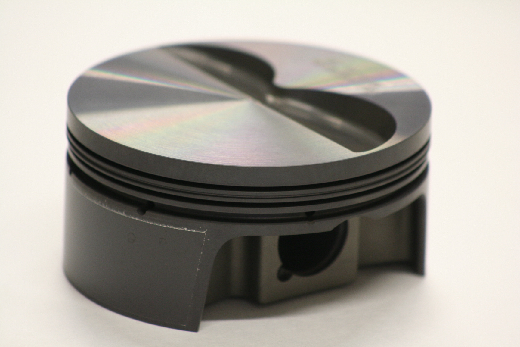
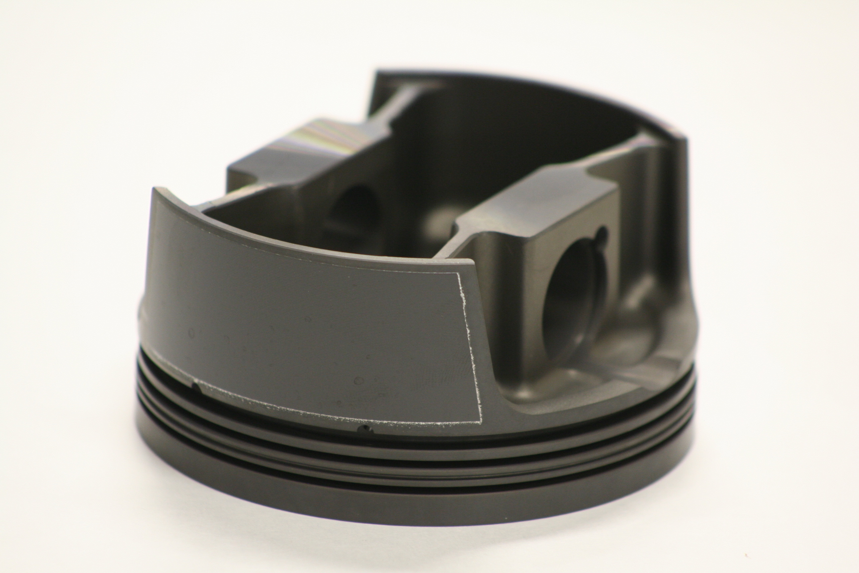
objectives and are lighter than H-beams. I went with Mahle forged
aluminum pistons. The pistons I bought weigh about 408 grams which
is about 10% less than a similar spec'd SRP piston. The low
rotating mass of the piston and rod should promote better engine
longevity and hopefully smoothness. The pistons also have a
coating to help with piston slap, which for a 331 shouldn't be as
pronounced as if I had chosen to go with a 347 stroker.
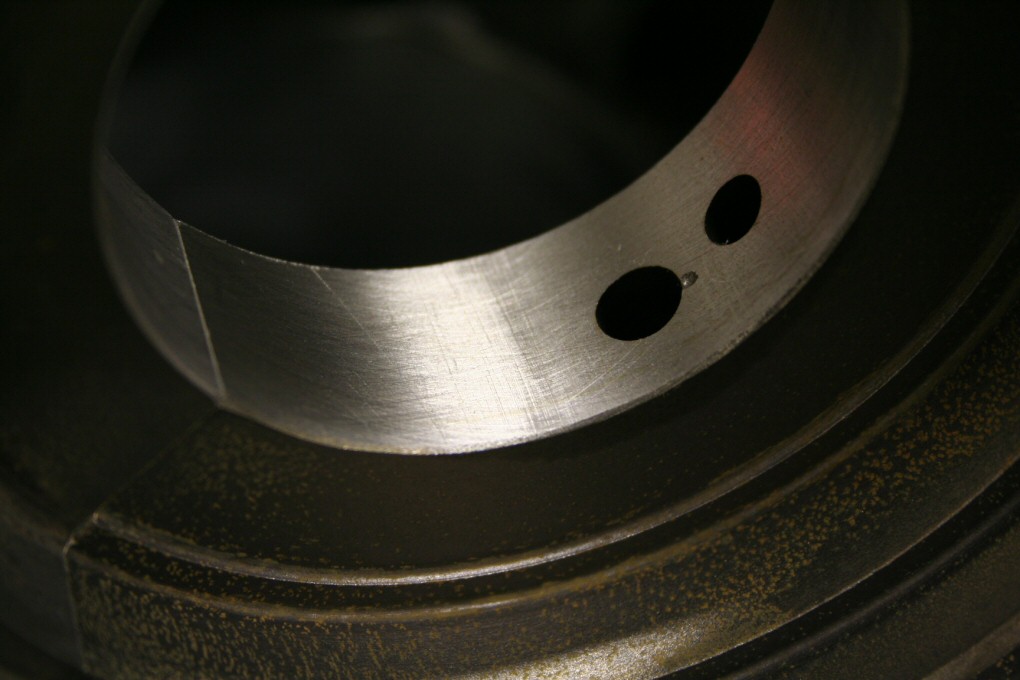
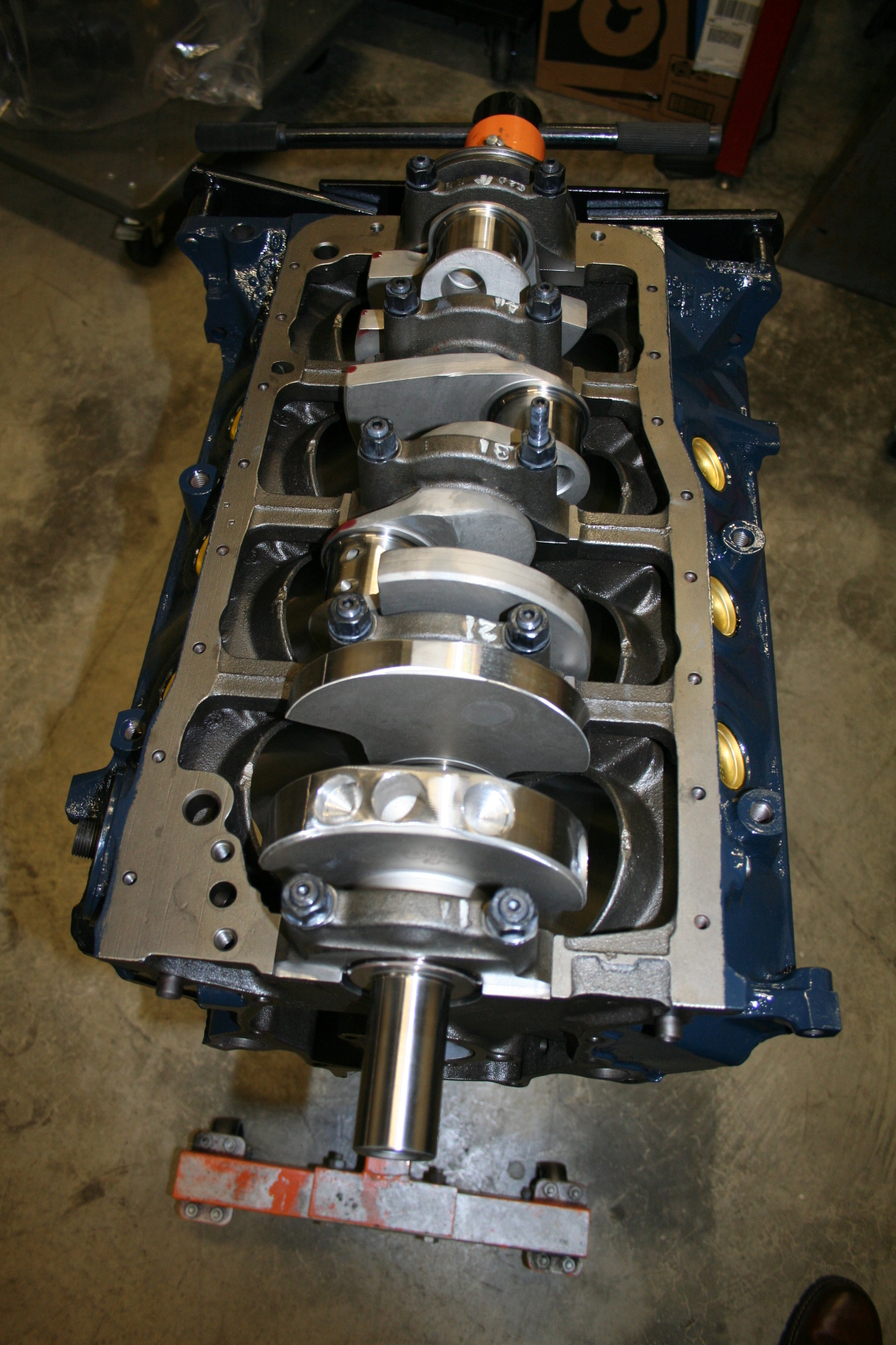
3/14/08 - The rotating assembly
was sent over to SR
Racing for a balancing job. They only needed to do work on the
crank as the rods and pistons were already in spec. To achieve
balance, SR did a combination of drilling and turning on a lathe to get
the crank balanced. The crank was then installed and so far so
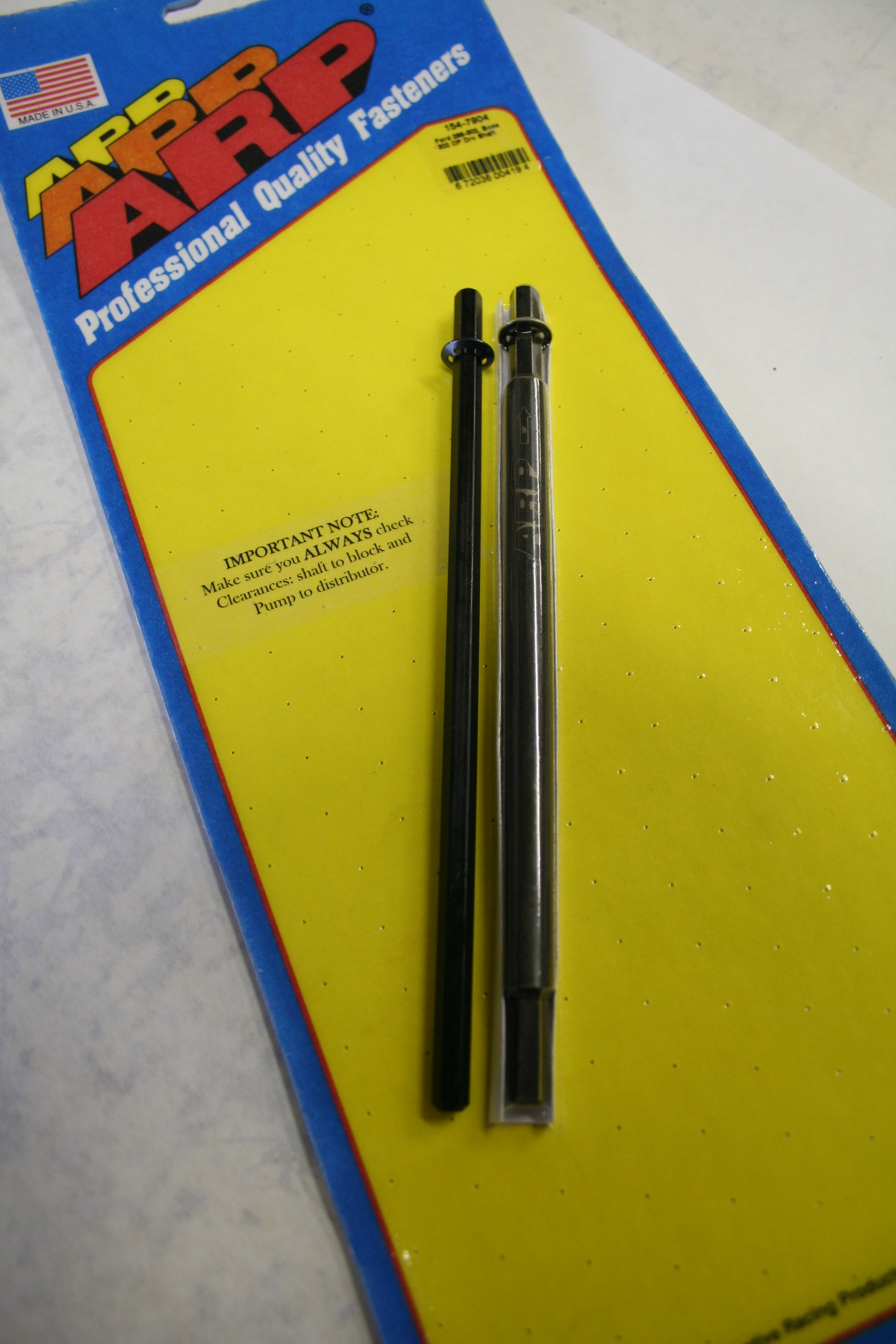
good. I also ordered a new oil pump. I went with a Melling
Select as they are supposed to be a bit more substantial than the
regular Mellings. The pump drive shaft that came with it was
pretty wimpy. Being that this is a weak spot/critical spot for
small block Fords, I replaced it with an ARP shaft. Visually, it's
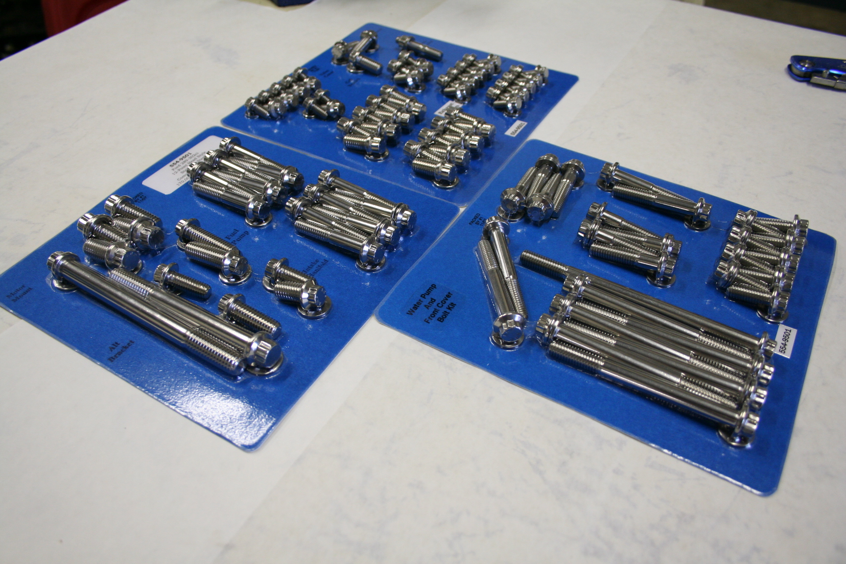
clearly stronger (thicker). I also had to order a bolt dress up
kit. All ARP stainless steel hardware is going in this engine
(from looking outside of the engine). We found a stud on the
center main cap (the stud that holds the end of the pick up tube) was a
little too long. We'll cut that later once we start putting in the
rest of the parts.
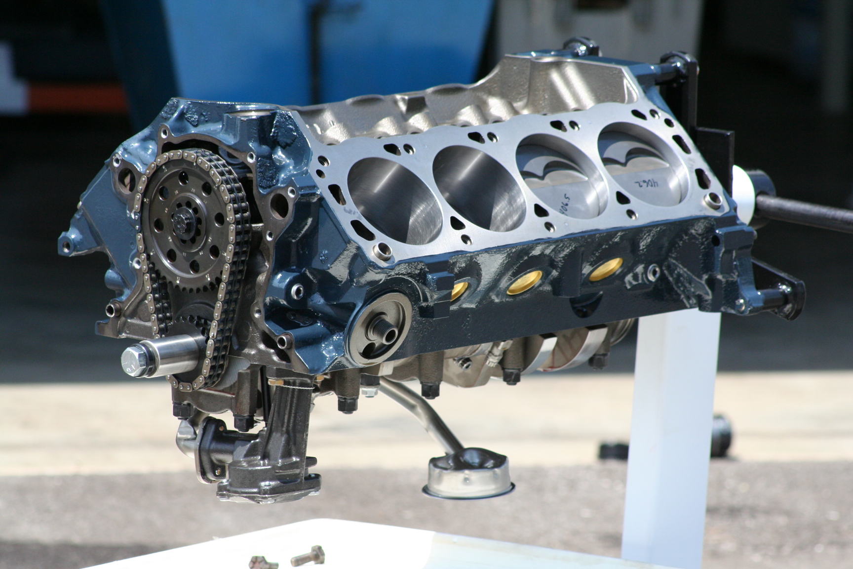
3/28/08
A few things to update... The camshaft has been ordered from
FlowTechInduction. I'm looking for a power band of
2300-6500rpm. The oil pump was tested and the bypass valve was set
at only 45psi. Kennedy Performance was smart enough to check that
now and is adjusting it to have a 60psi threshold instead. A
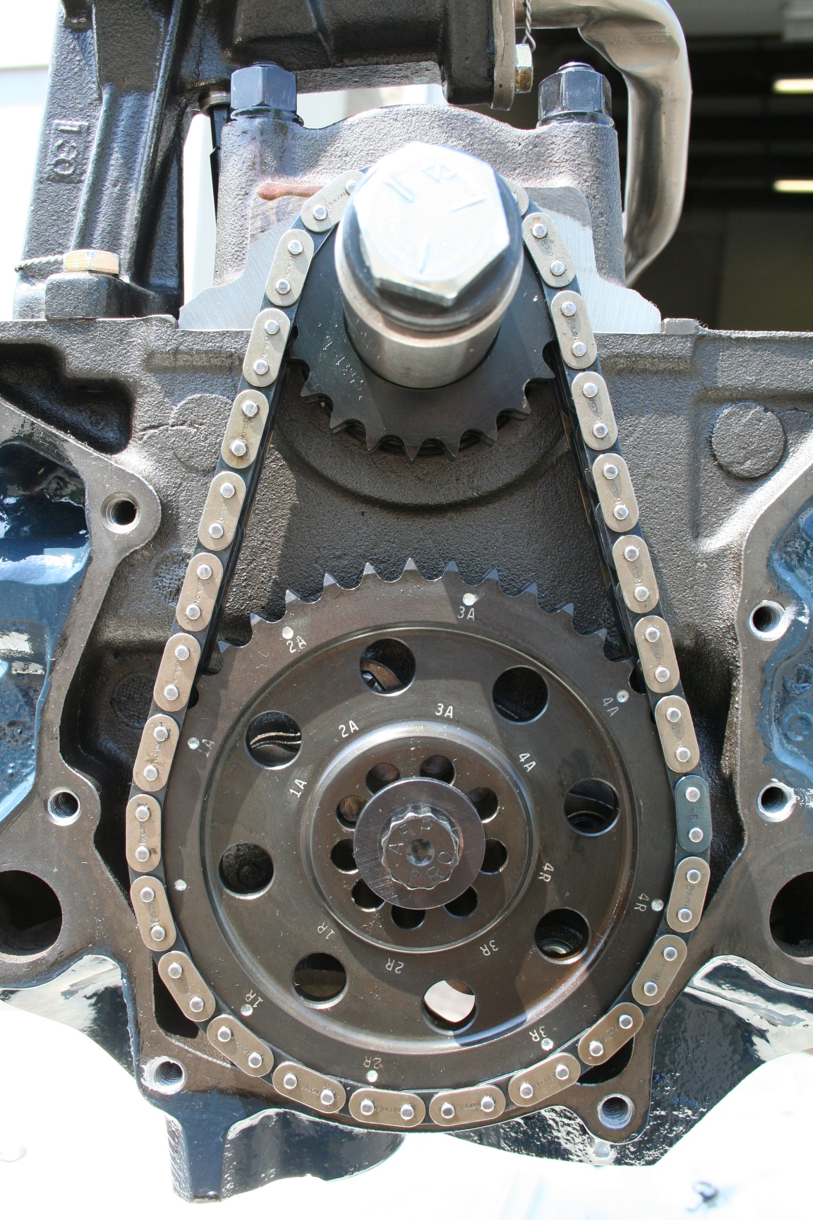
ProGear Camdex timing set has been ordered and received. Very nice
looking set. The timing cover, alternator/tensioner bracket, and
PS pump brackets have been powder coated silver. The smog pump has
been deleted with an idler pulley. All pulleys are in the middle
of being converted to aluminum ones for cosmetic reasons. I'll
probably have them all clear anodized to make them last. Overall,
the short block should be done pretty soon. I'm guessing about 4
weeks from now.
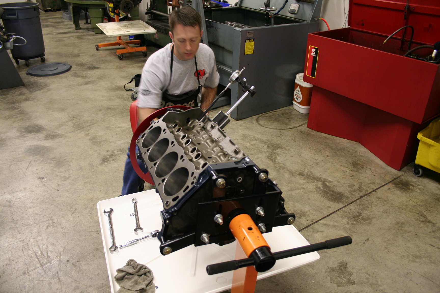
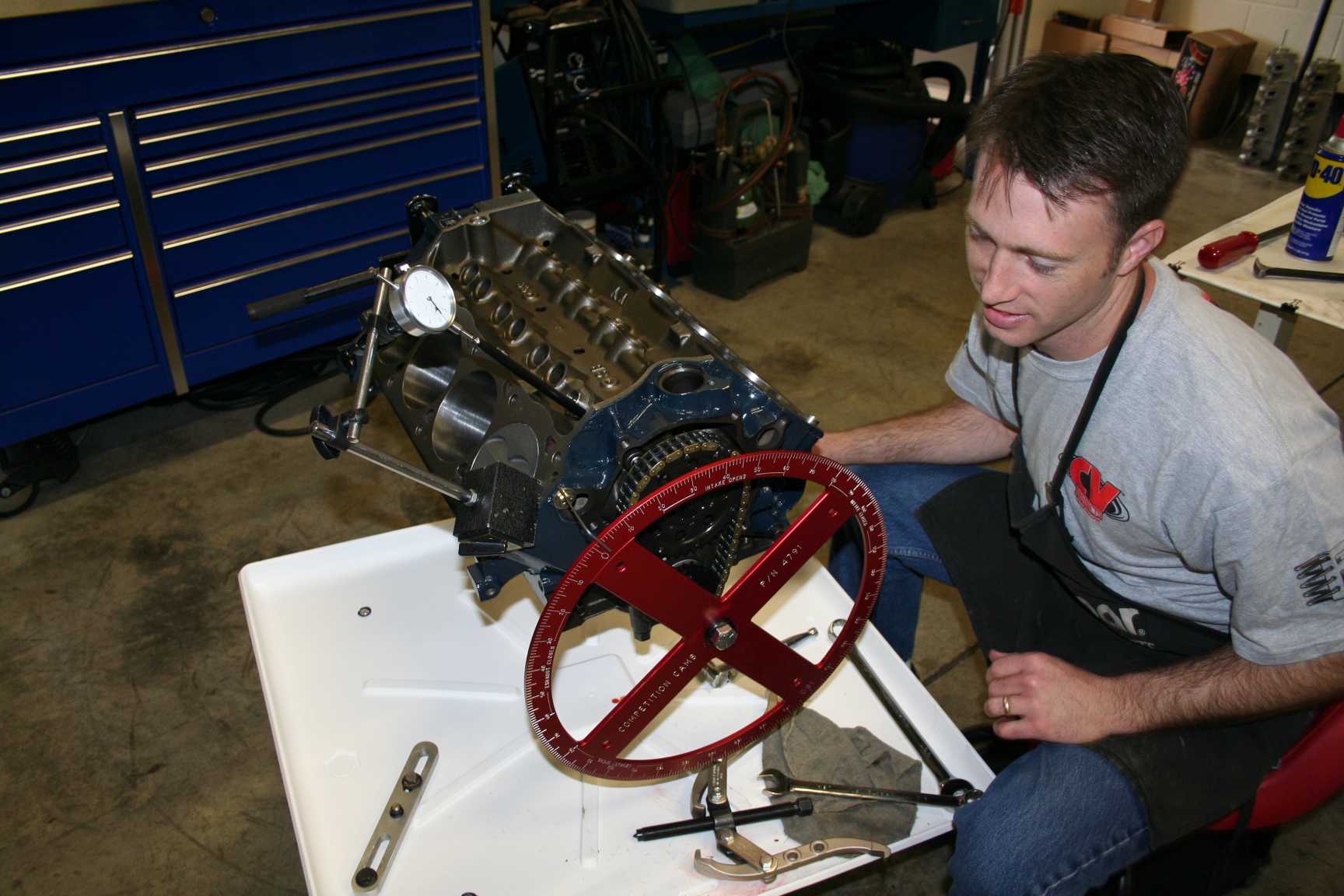
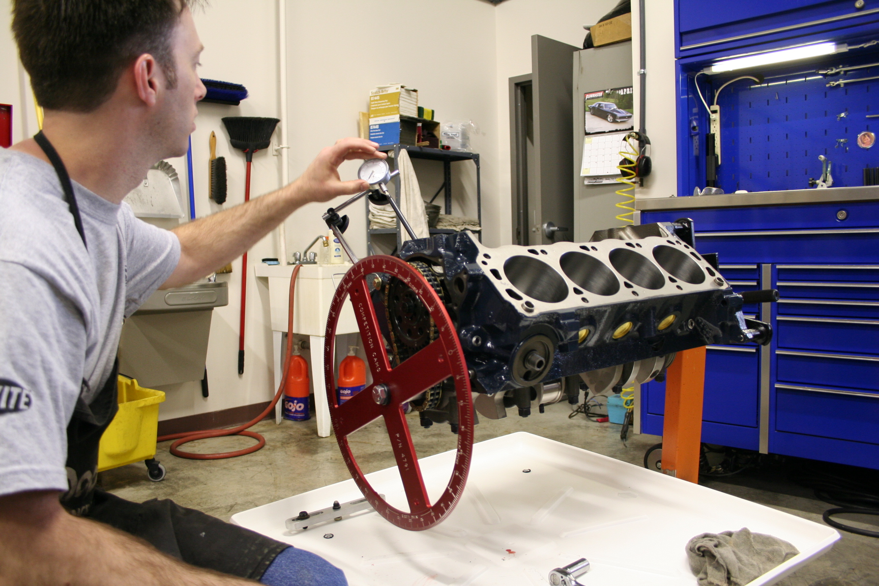
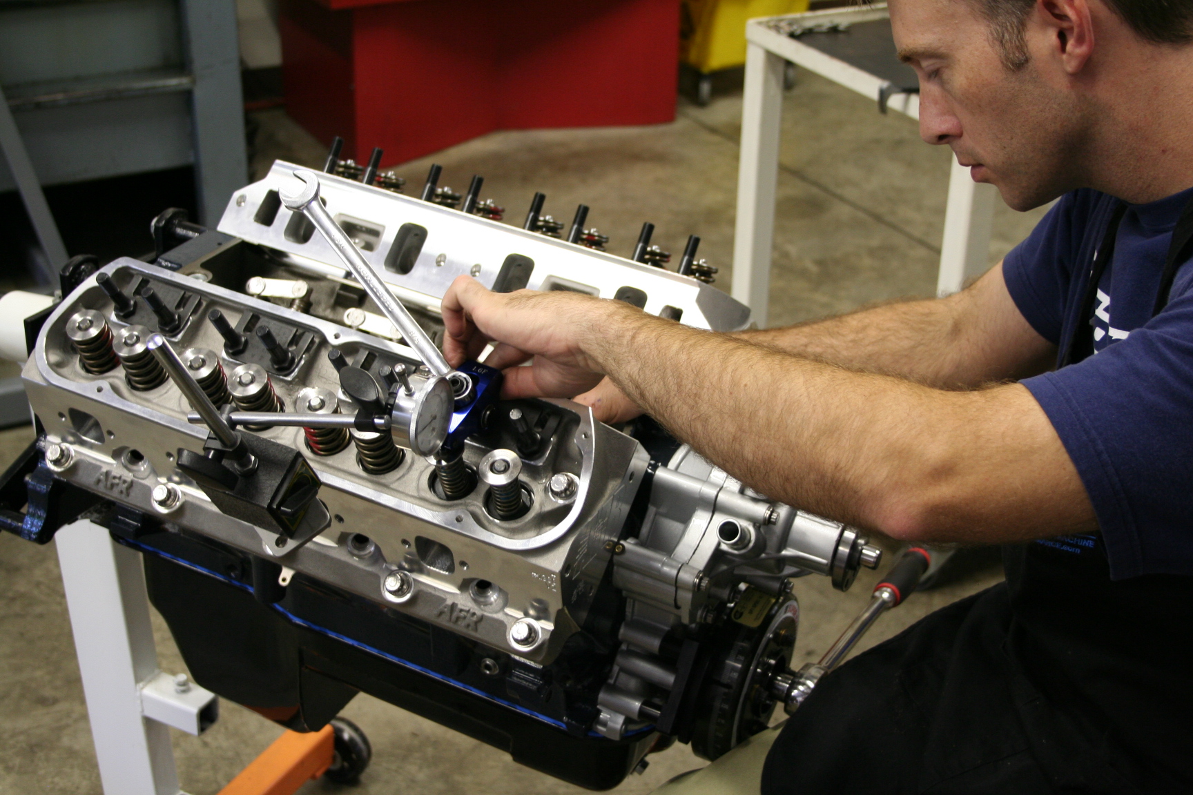
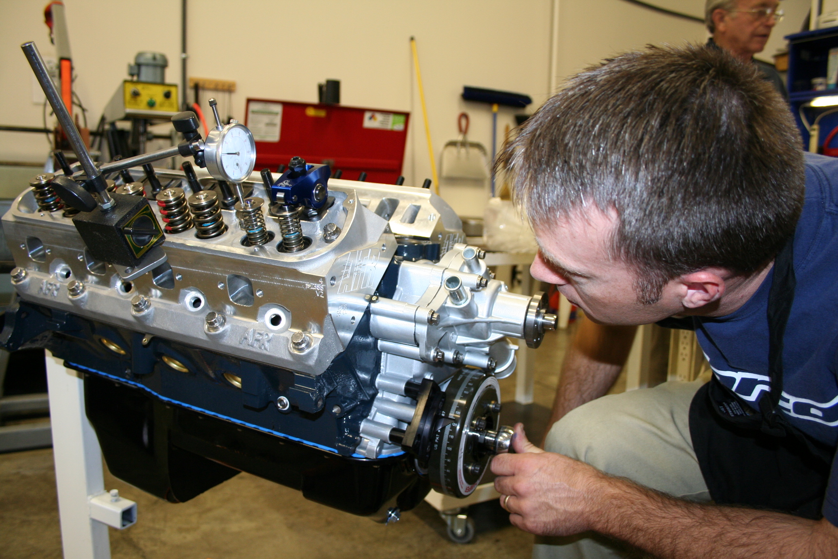
4/11/08 The
camshaft has arrived! It's now been installed and degree'd
by Chad at Kennedy Performance. Due to the line honing,
the Progear timing chain (stock length) is a little loose so a
slightly shorter one (0.005") will be swapped out. I
want to start out with as little slack as possible; it will
eventually stretch some so I want to minimize problems now w/ a
tighter chain.
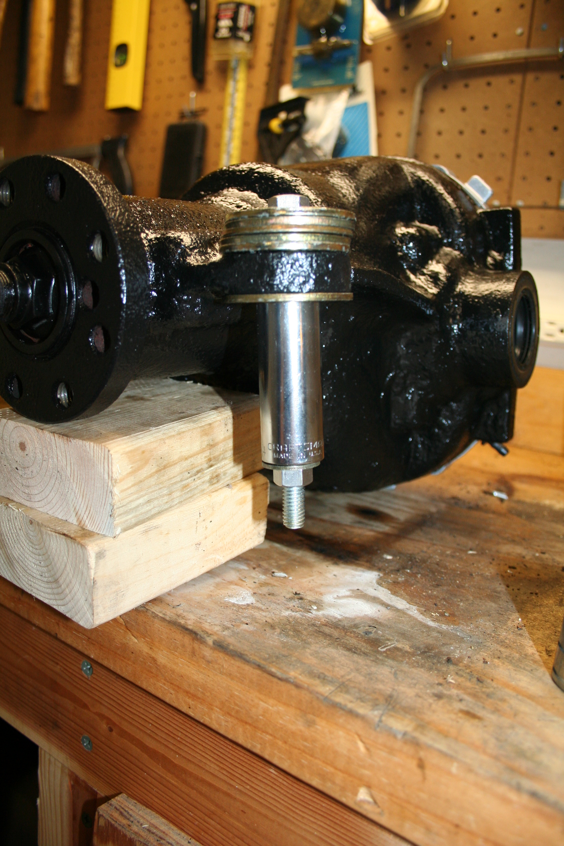
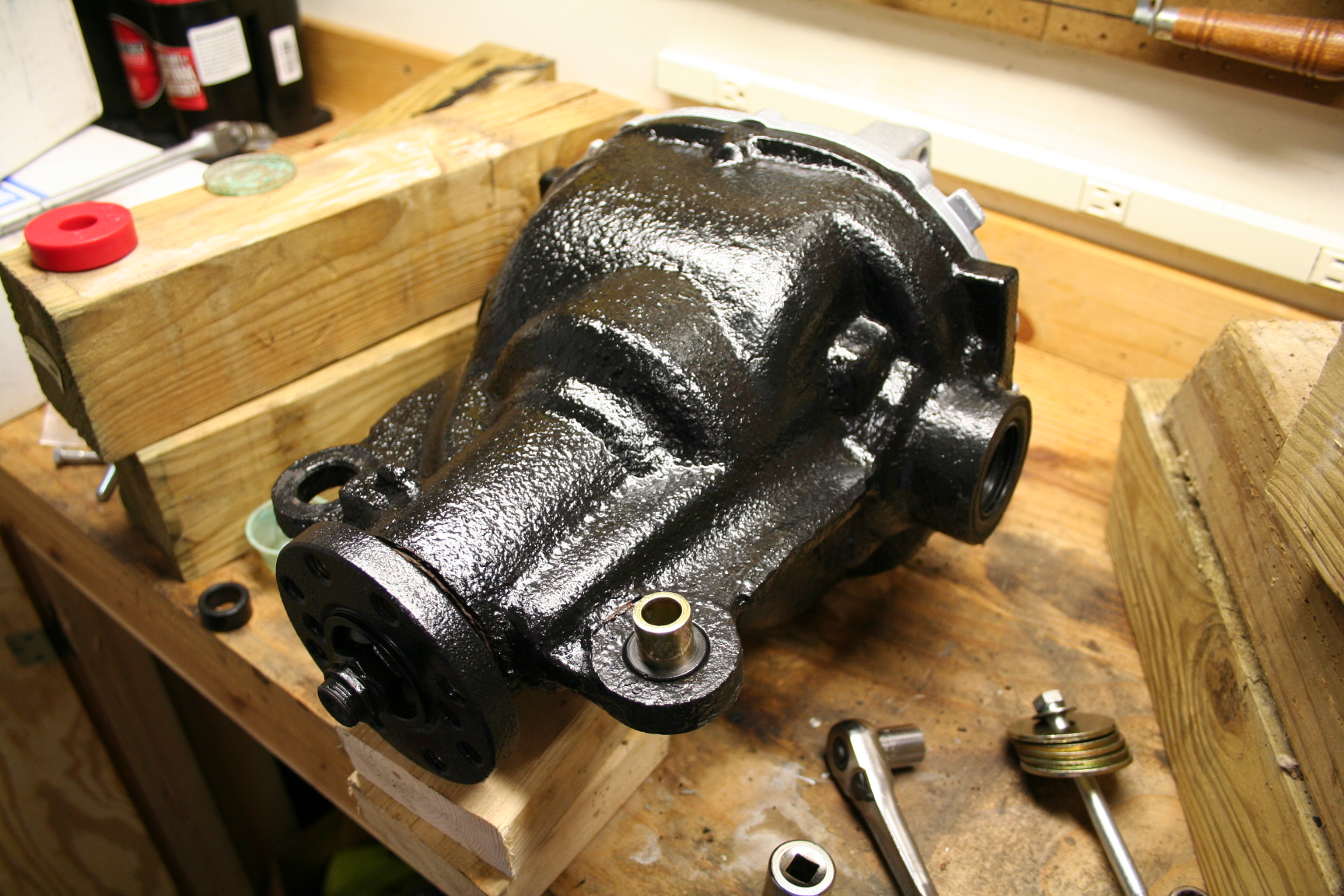
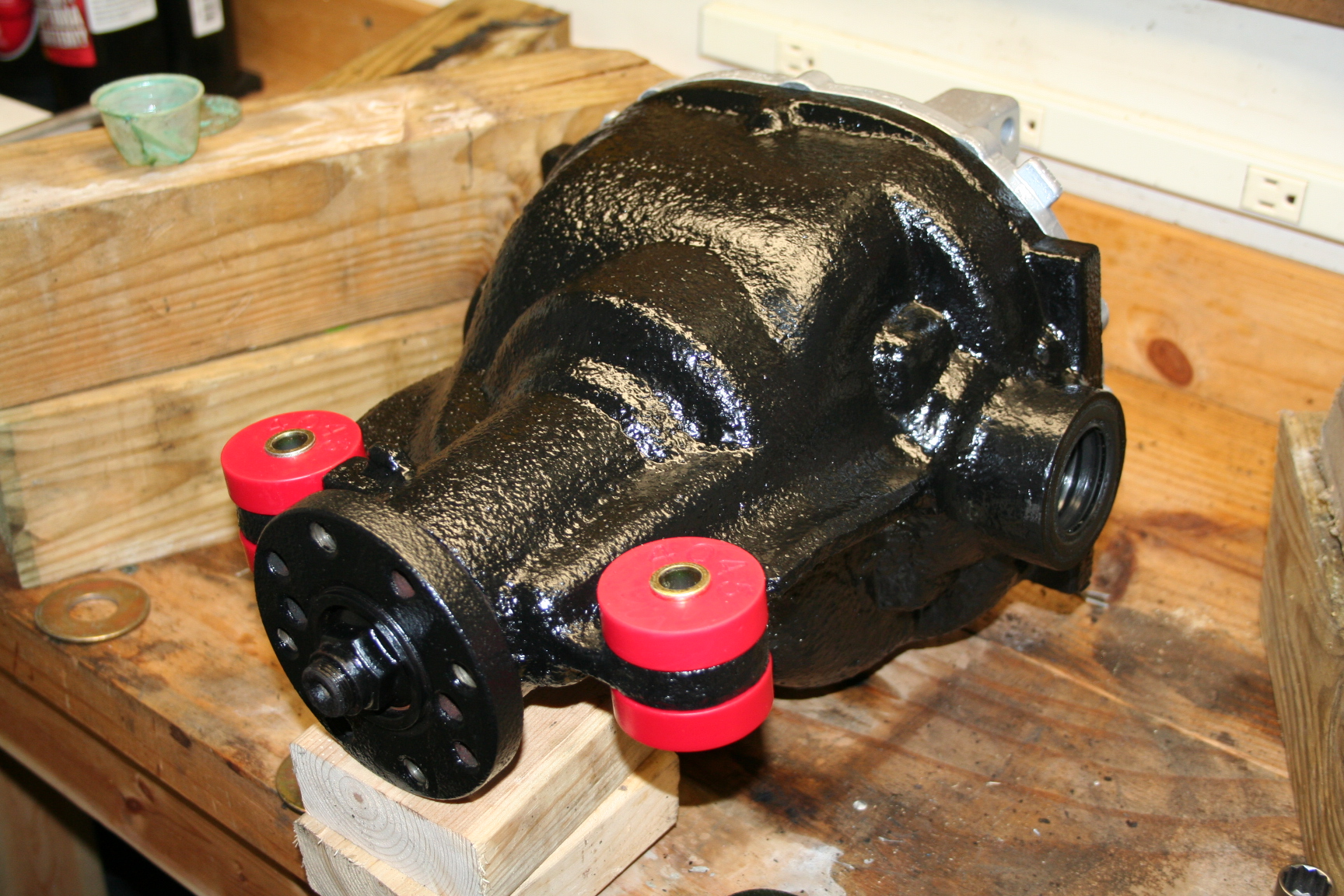
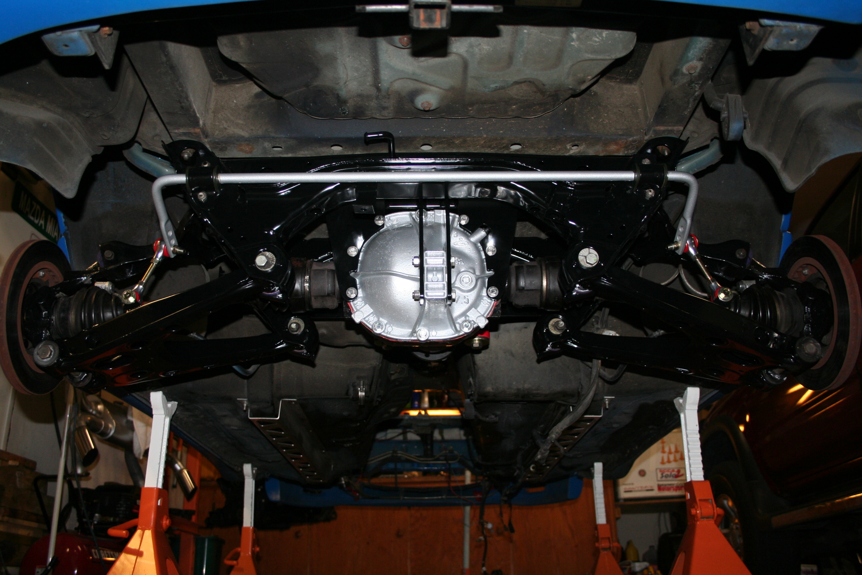
4/12/08 I went
ahead and did a little clean up work on the differential I
got. The main housing got a cleaning and repaint of POR-15
Chassis Black. I took the diff cover to my local powder
coater for a coating of the same silver on my timing cover and
engine accessory parts. I still need to swap out the
internal open diff for a TrueTrac but I just had to clean it up
now.
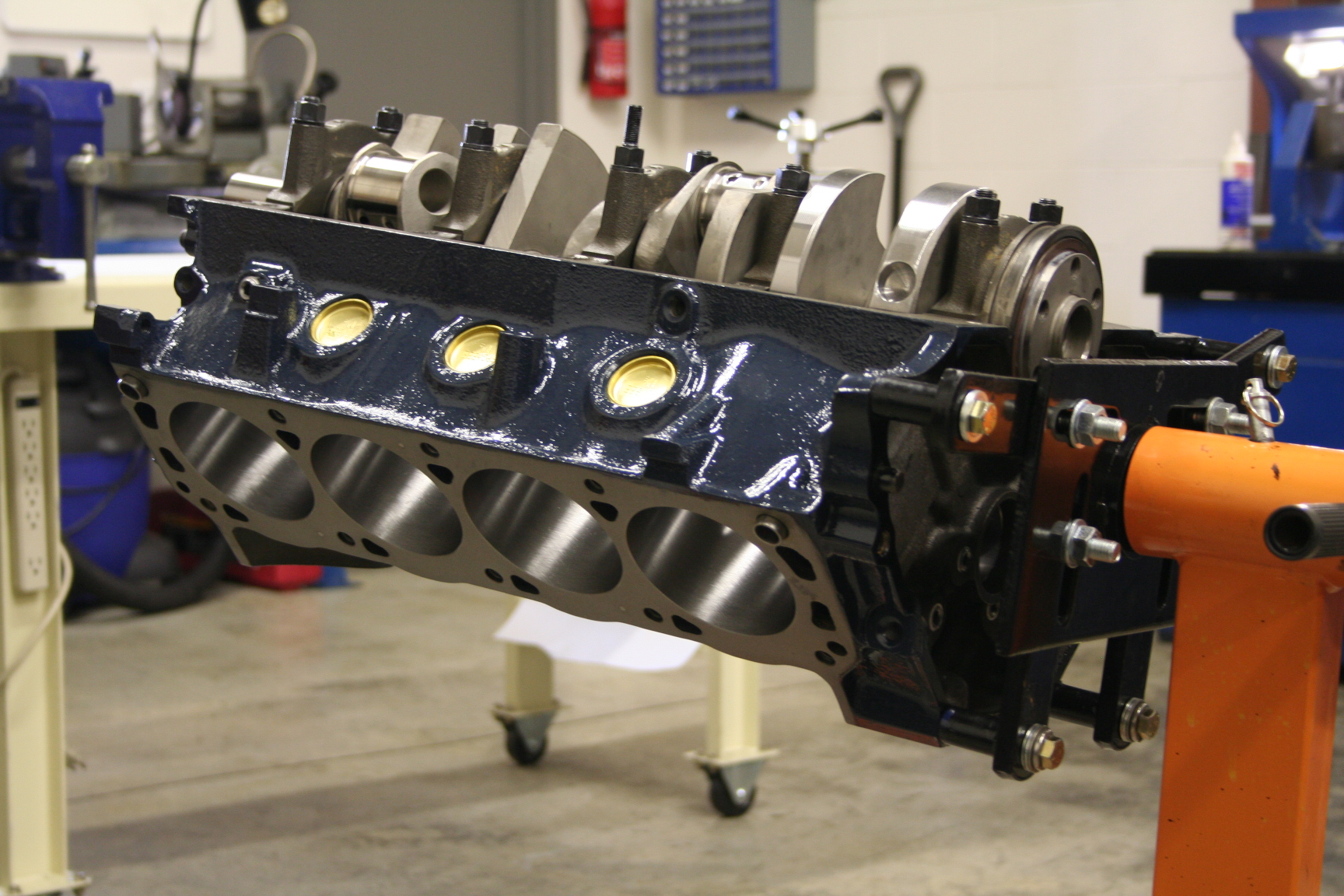
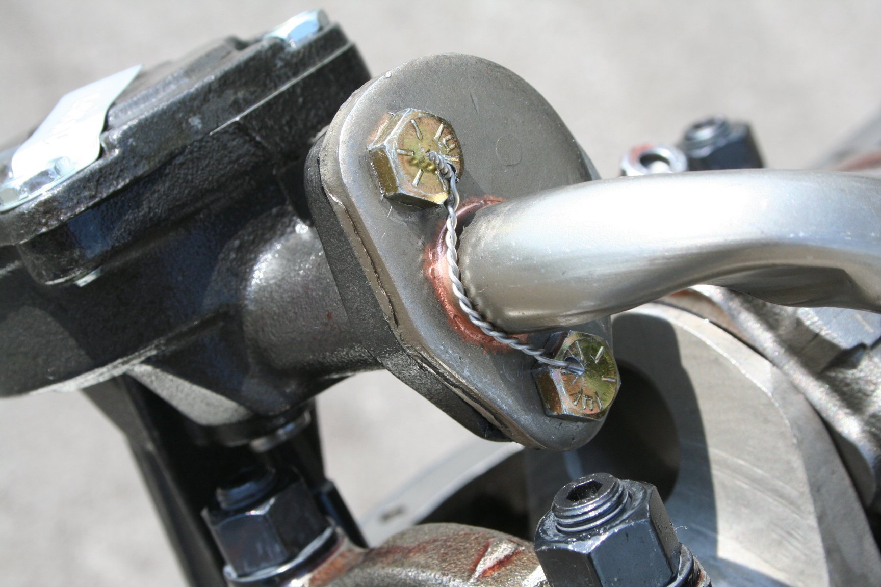
4/24/08 The
short block is complete. Kennedy Performace did
a great job. Lots of attention to detail. Even the
oil pump bolts are wire-locked in case something were to come
loose. We ran into a small problem with the oil pan and
the ARP rod cap bolts. Martin at Monster Miata updated his
oil pan to now have enough clearance for the ARP bolts, however
the pan we received had a slight bend under the #1 rod cap and
was causing some interference. It was in a weld joint with
a wall going 90 degrees down from it so forming the metal down
with a hammer wasn't successful. A careful grind of the
pan was done and now there is about 0.0060" clearance
between the rod bolt and pan. The new timing chain set
with the 0.005" shorter link is installed as well as the
remaining rods and pistons. The oil pan went on as well
as the timing cover and water pump. Gotta love those shiny
stainless steel ARP bolts.
6/11/08 There's
not a lot to report right now. The engine build is
awaiting the heads which will probably be ordered next
month. During this time, I've be doing a lot more research
with respect to the valve train, carburetor and tranny.
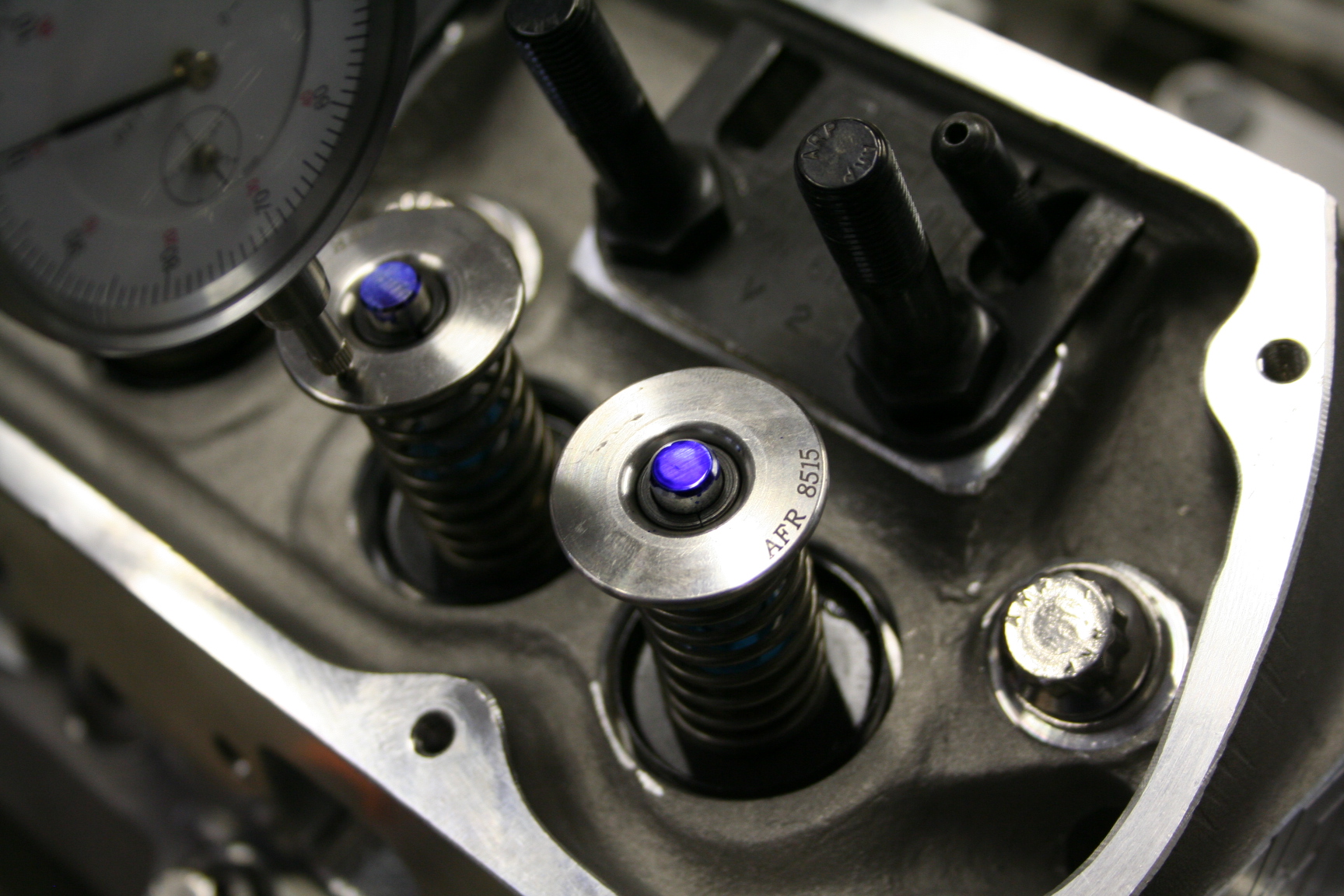
The valve train clearly
needs to be up to the task that my camshaft will require.
Valve springs must deliver enough seat and open pressure to
eliminate float and bounce, so I'm using an optional upgraded
spring set AFR offers delivering 155lb on the seat and about
400lb at full lift. Will use titanium retainers to
minimize mass in the valvetrain. Thick walled pushrods;
not sure yet which ones. Link-type Crane hydraulic lifters
to withstand the high forces associated with the high ramp rates
of the cam. 7/16" rocker studs to handle the higher
forces.
Looking for a carb that is
about 650cfm, probably vacuum secondaries and an electric choke
to achieve great overall power performance while keeping it streetable year 'round. Expecting to look for a good tuner carb, but may
consider an off the shelf
unit from Holley. Considering BIGS
Performance , Competition
Fuel Systems, or Pro-Systems.
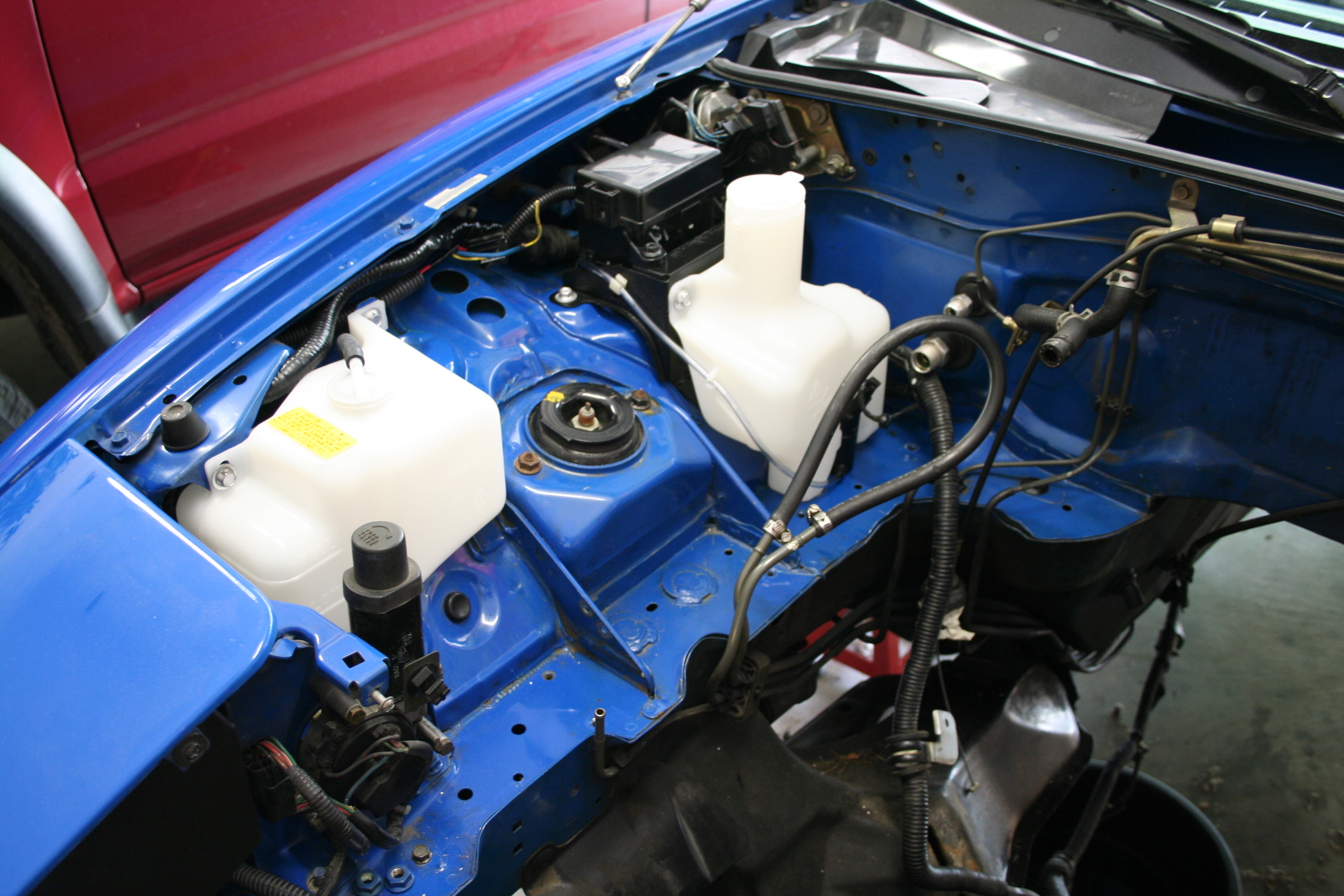
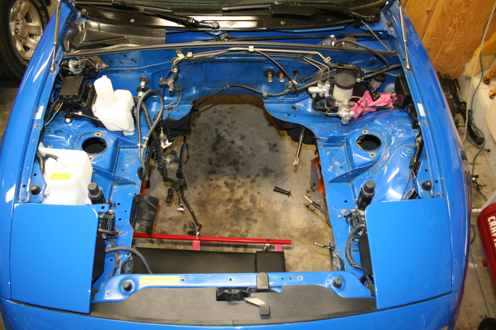
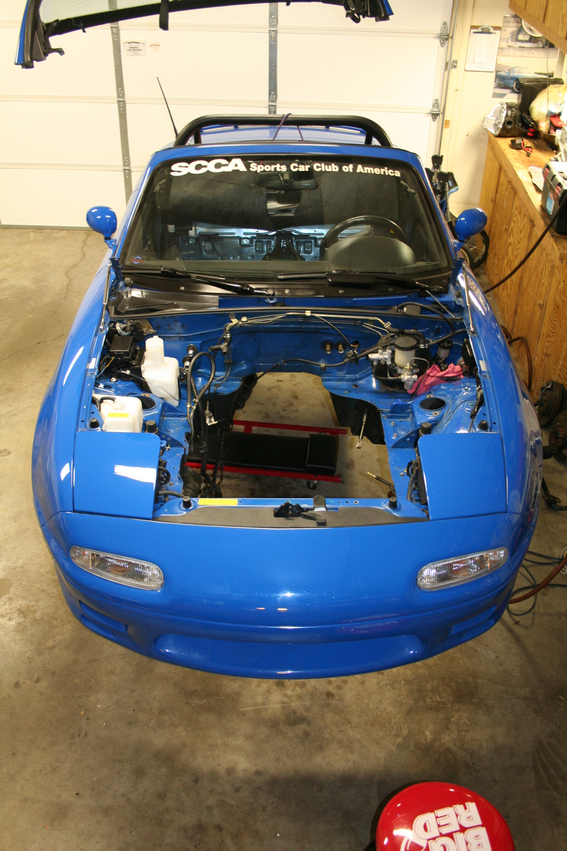
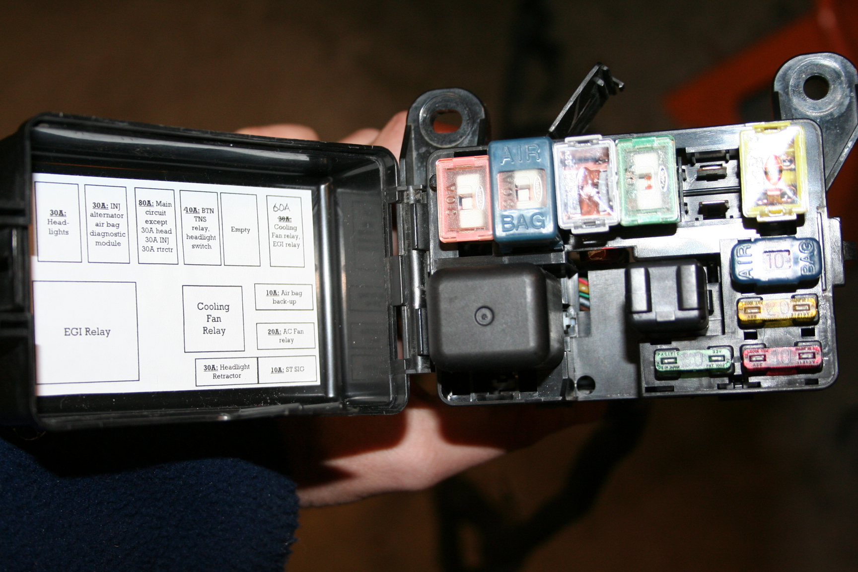
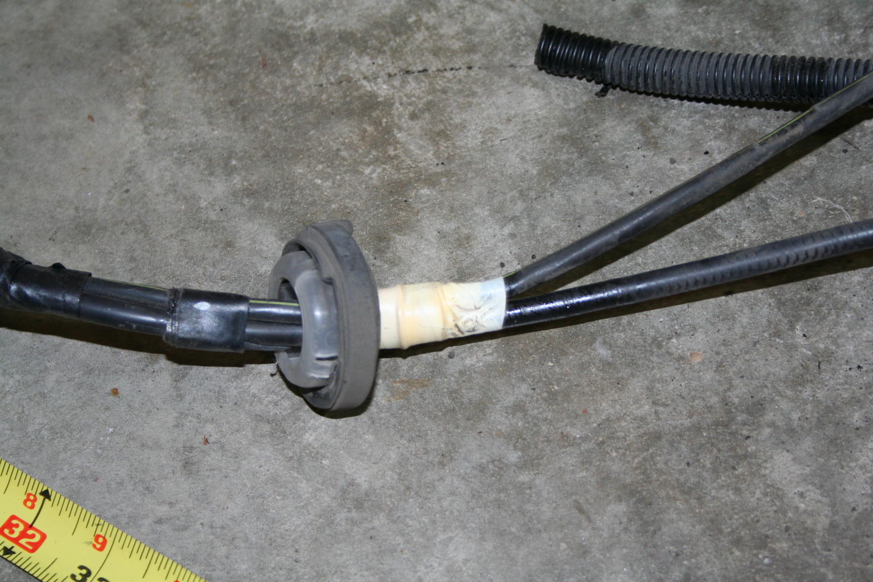
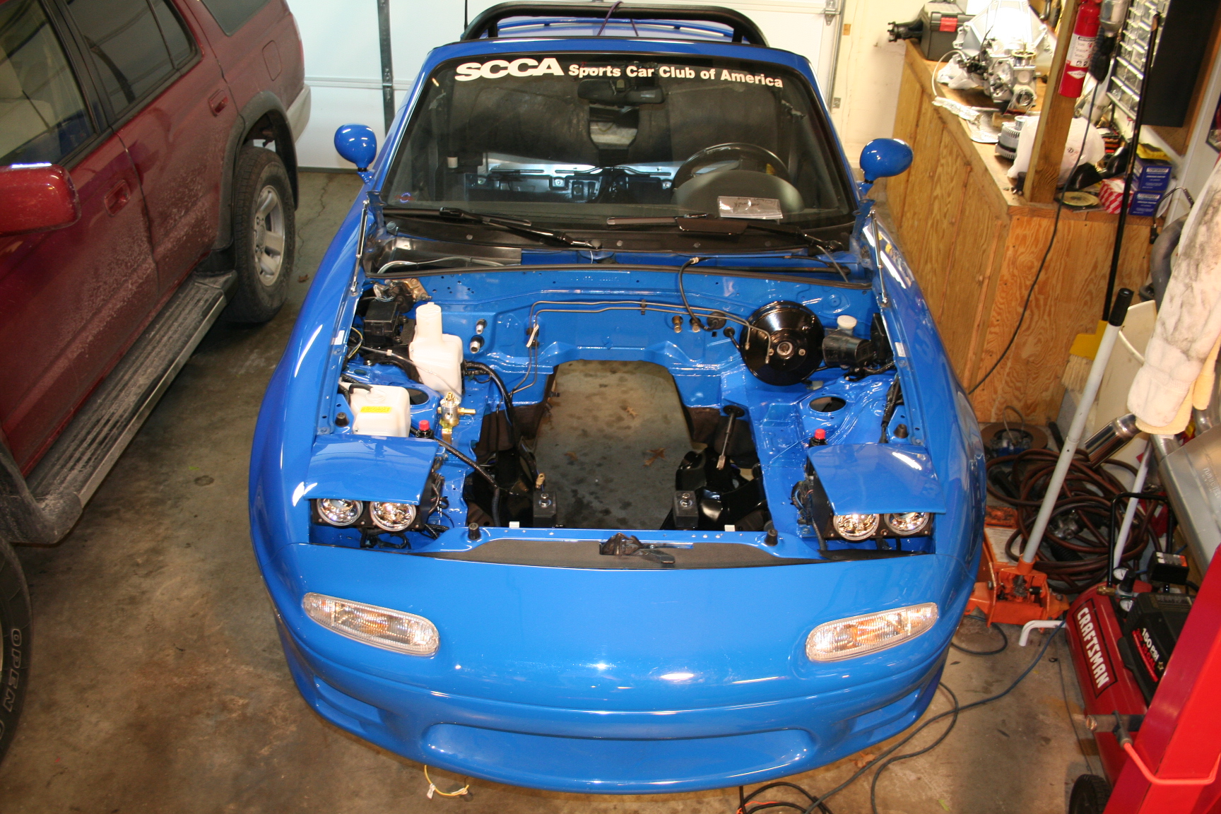
7/1/08 While
waiting to buy/save some parts for my engine, I started going
through my engine bay some. Since I'm going carbureted,
several wires and connectors associated with the original EFI
system are not needed so I've begun trimming the un-needed wires
from the harnesses (or removed certain harnesses
entirely). I still have not gone through the
battery/alternator/starter/ground wires but will probably save
that for once the engine is in and I've settled on where to find
a good path for those items. I'm also considering removing
most items in the engine bay for a paint job. Not sure
yet.
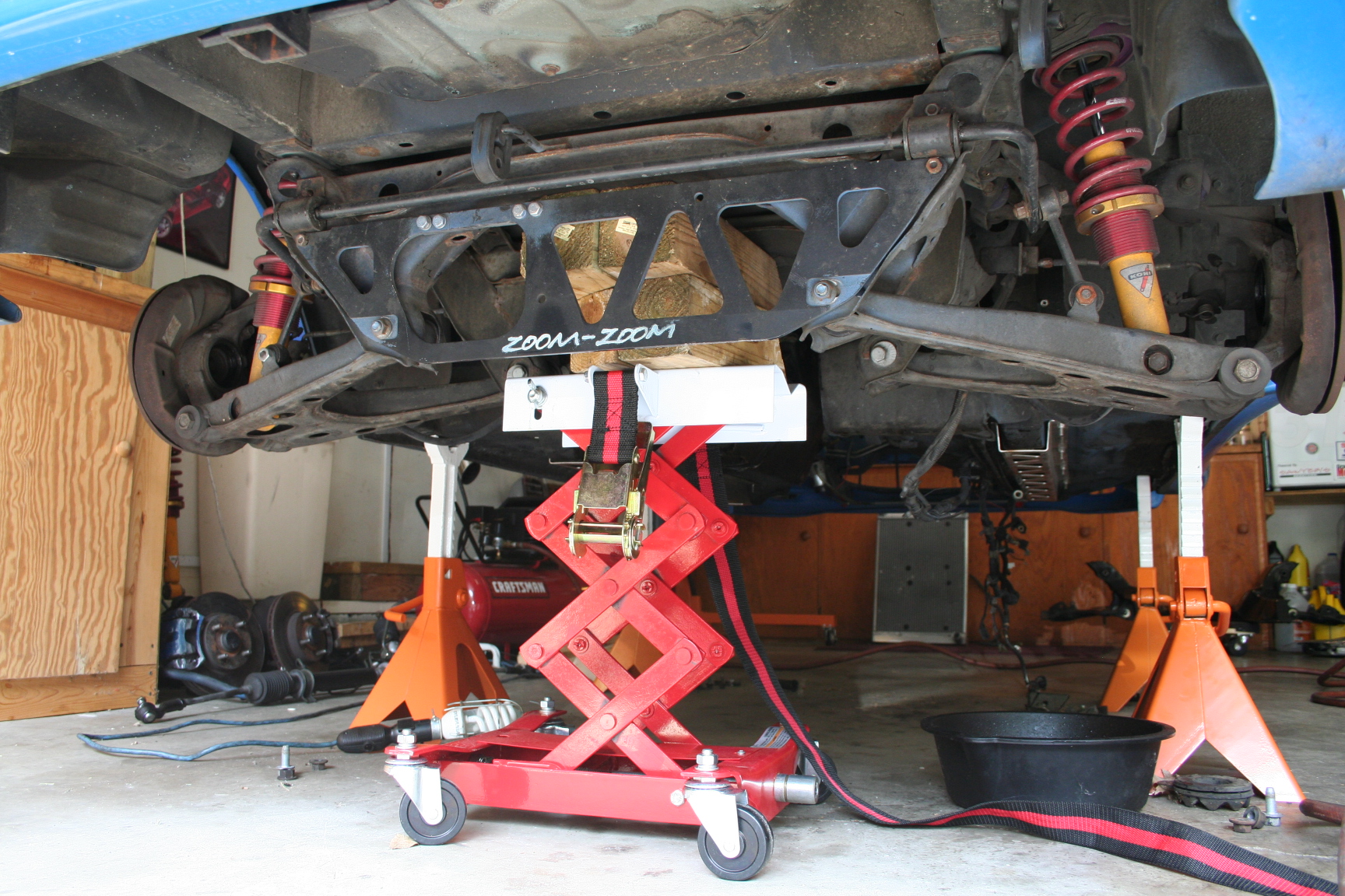
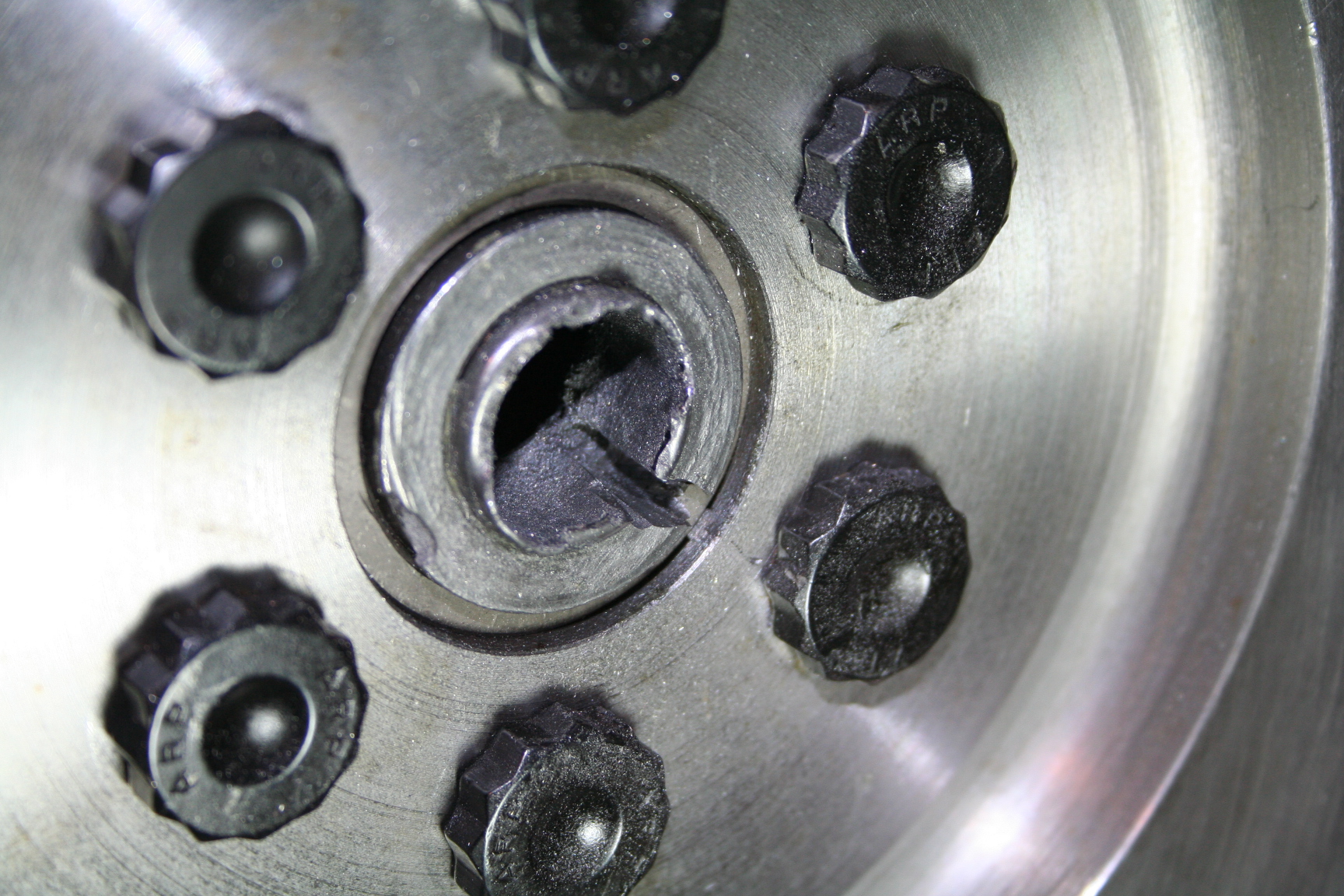
7/18/08 My good
friend Nigel has decided
to convert his V8 miata back to a 1.6L 4 cylinder for various reasons, but
a catastrophic
engine failure of his 302 initiated the decision. As a result, he and I have
decided to exchange some parts. It's a win-win situation
where I get some kit parts that he no longer needs, and he gets
some stock parts I no longer need. So, off I go
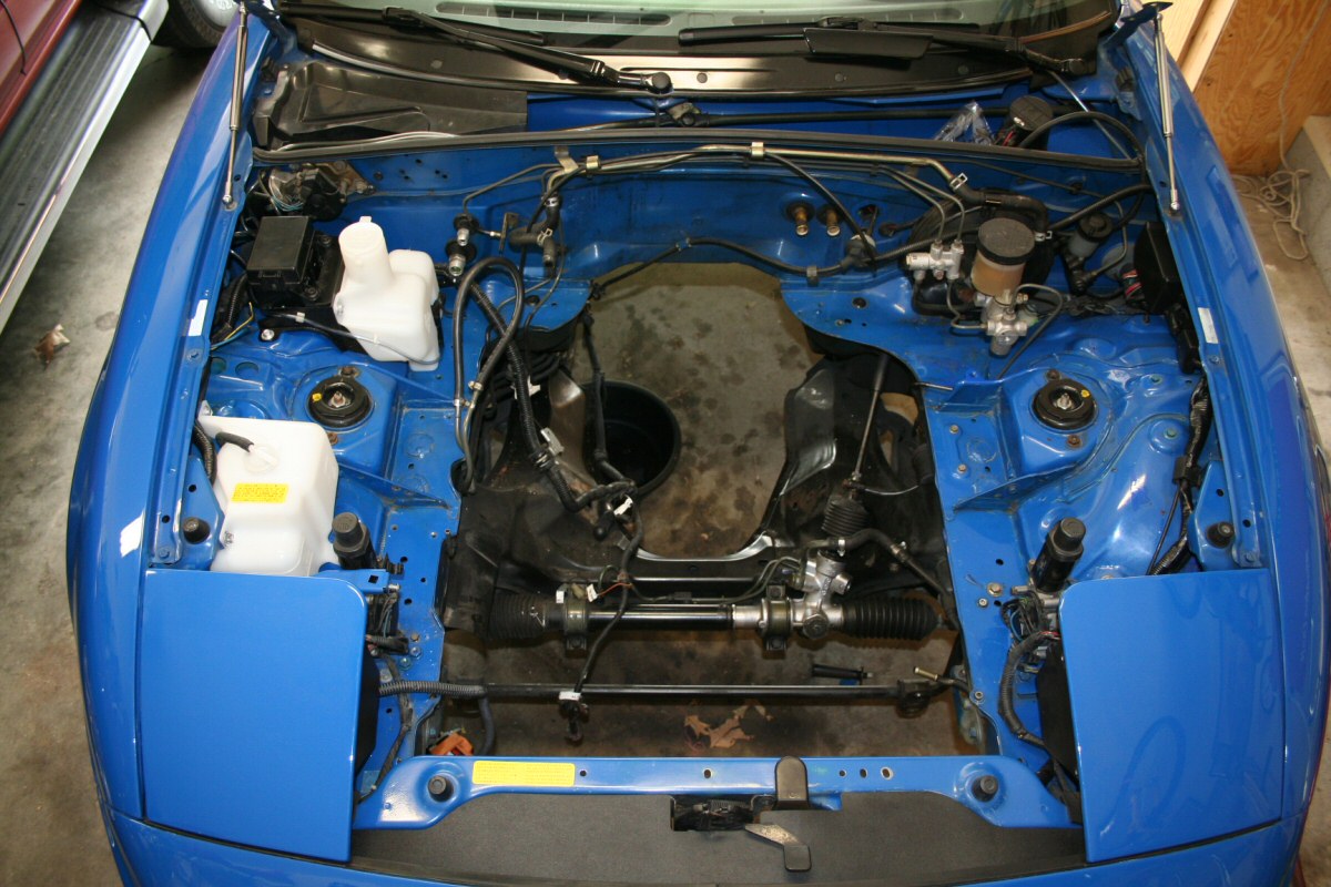
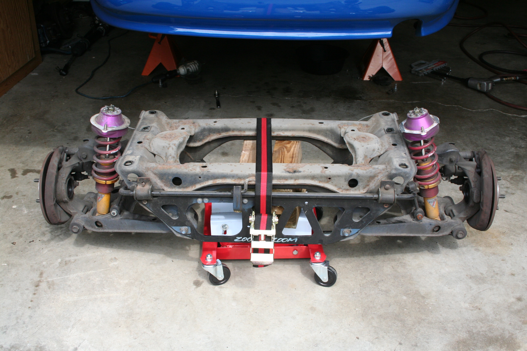
removing some more parts. The K-frame is a key part that
will be exchanged and I've pulled it along with various other
suspension parts. That engine bay is looking bigger!
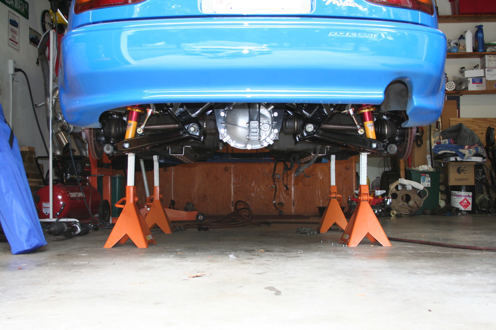
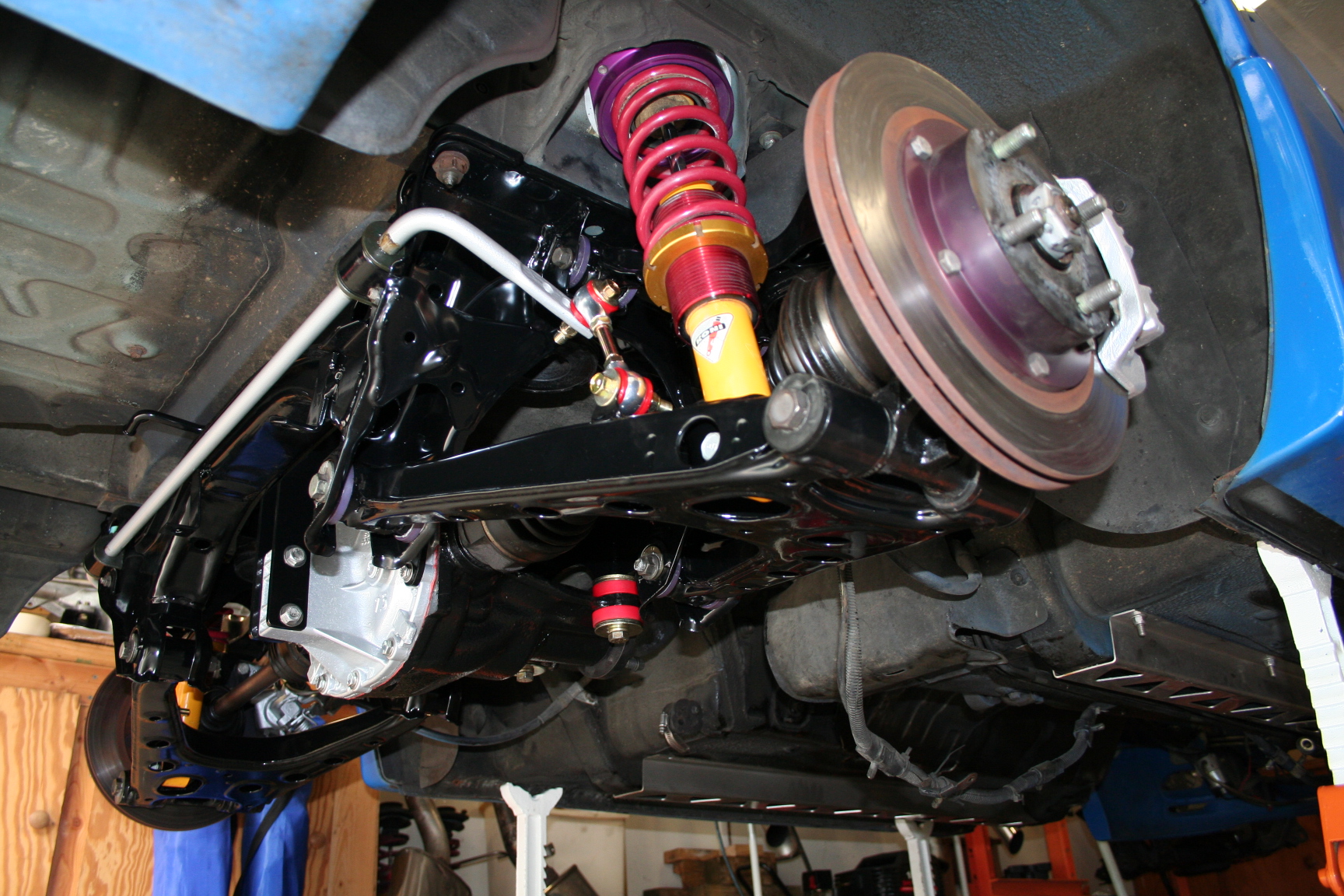
8/30/08 I
disassembled the rear subframe assembly, and cleaned it up a
bit. I got a little carried away and ended up having most
pieces powder coated. Most of the rear has been
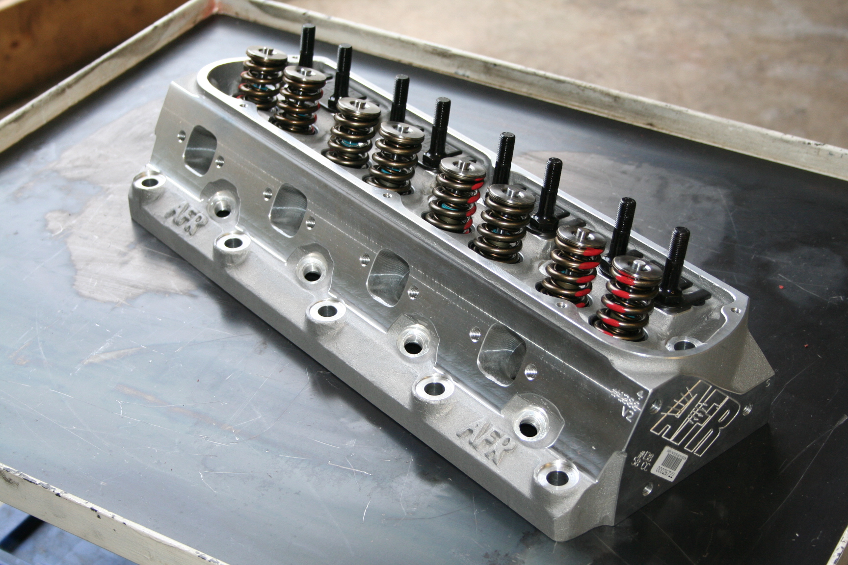
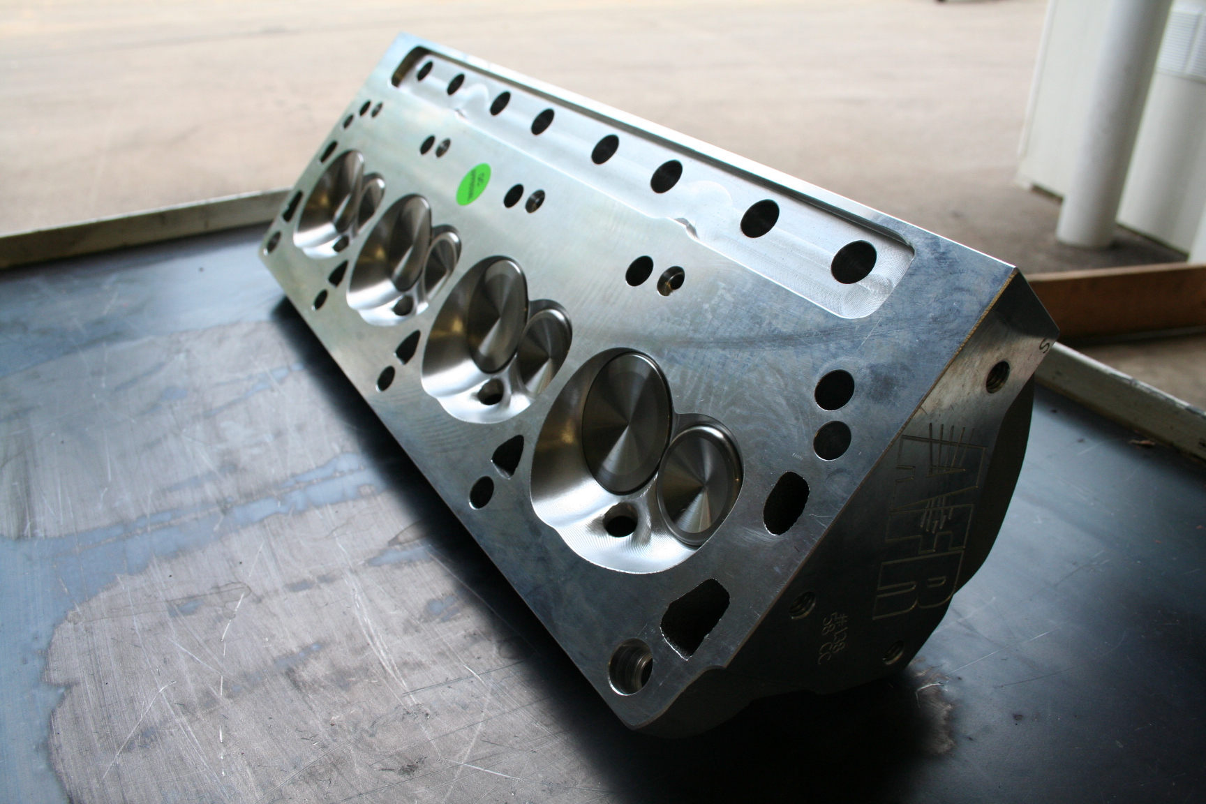
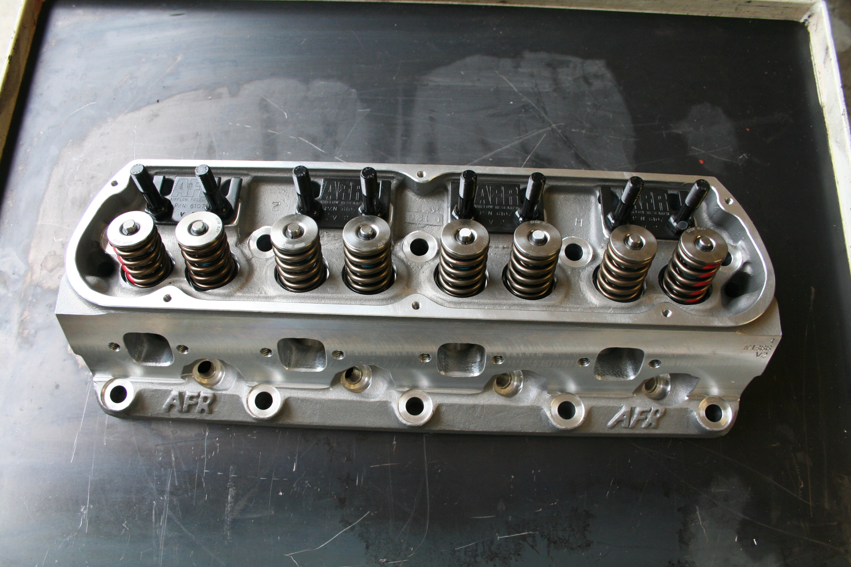
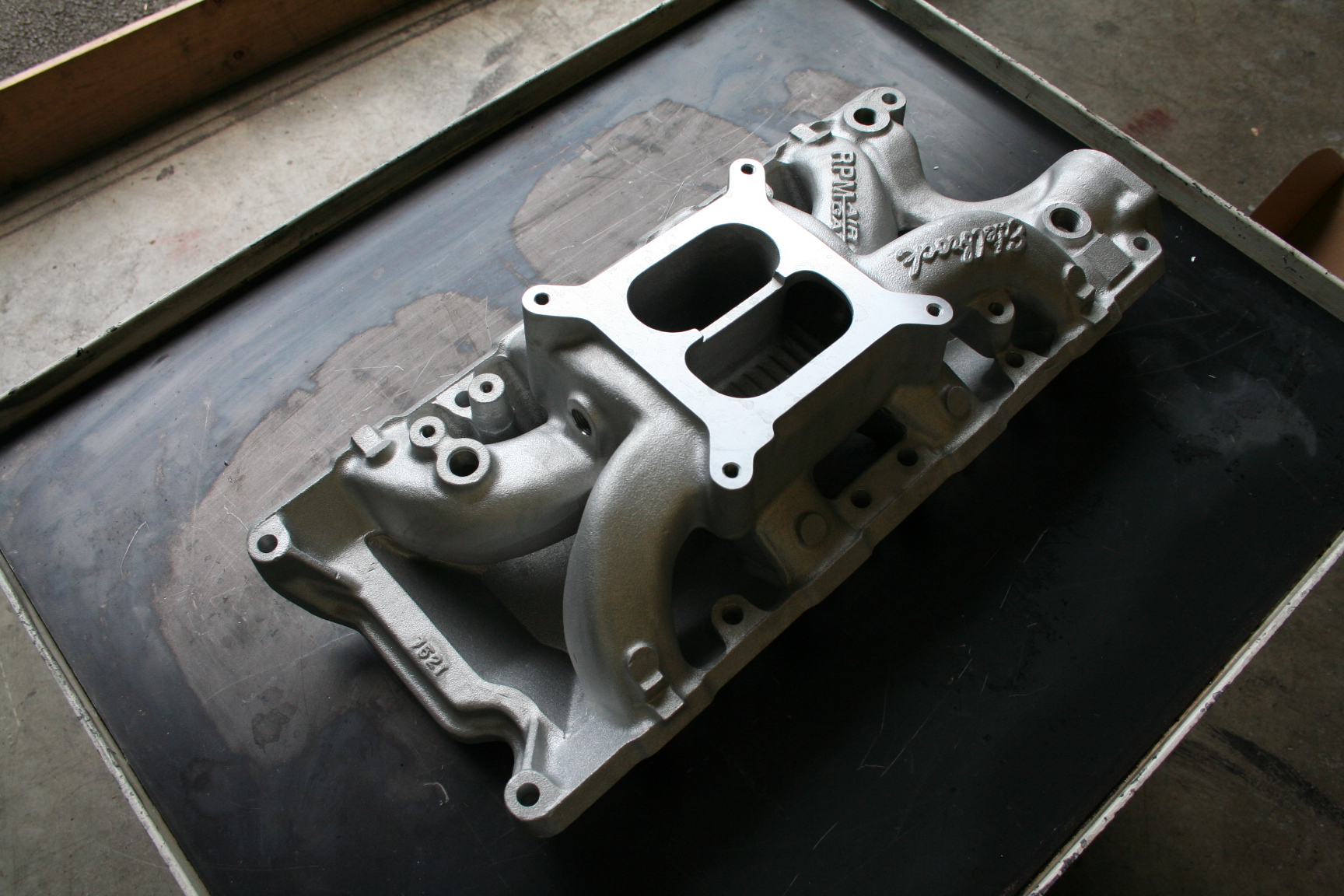
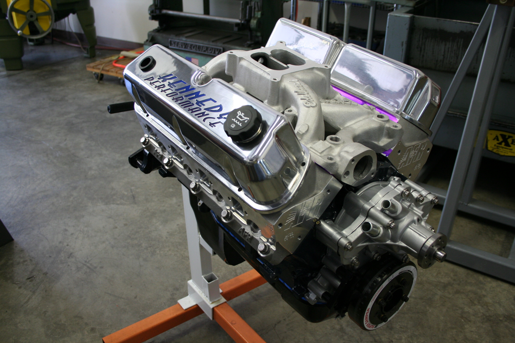
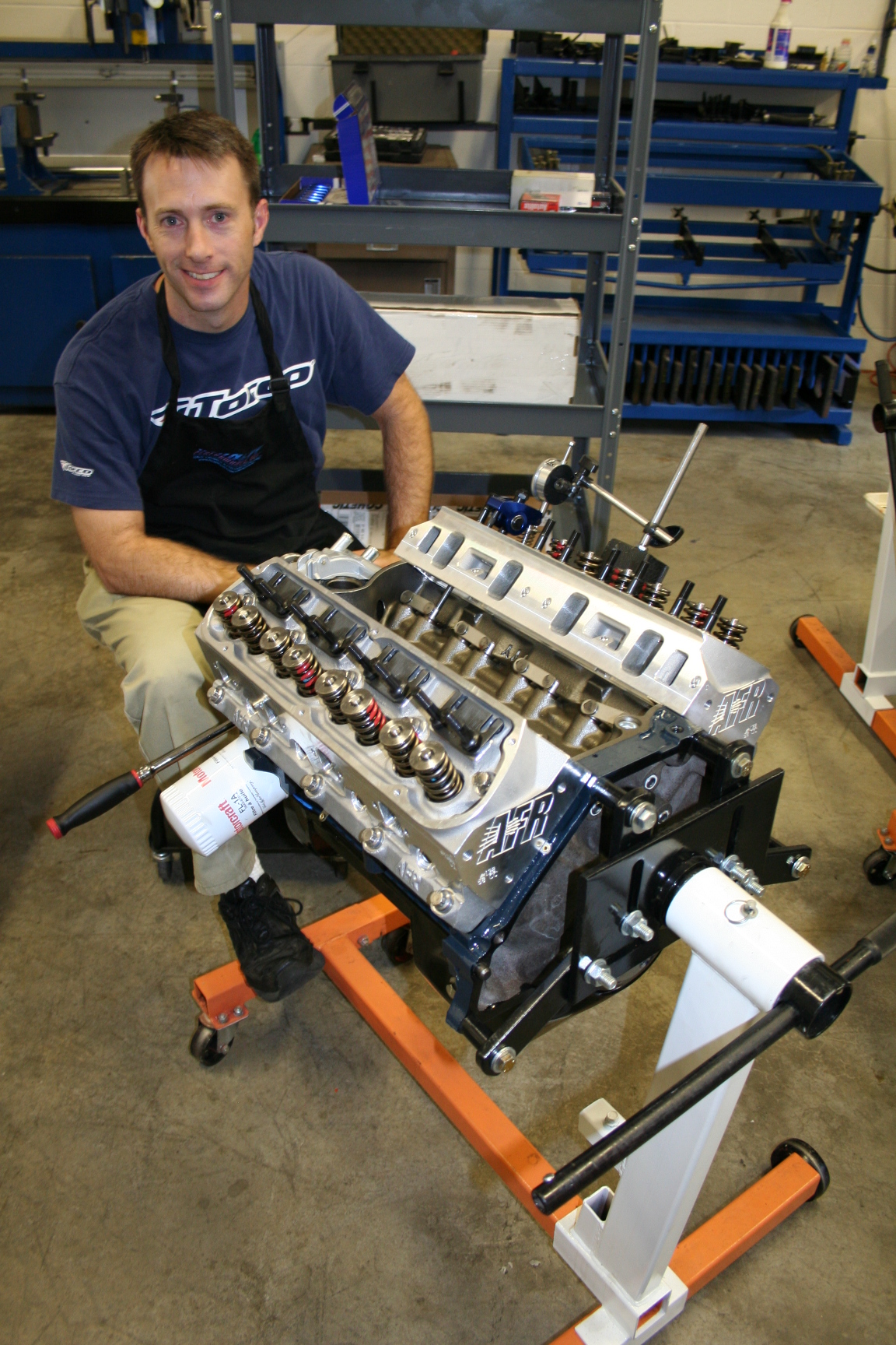
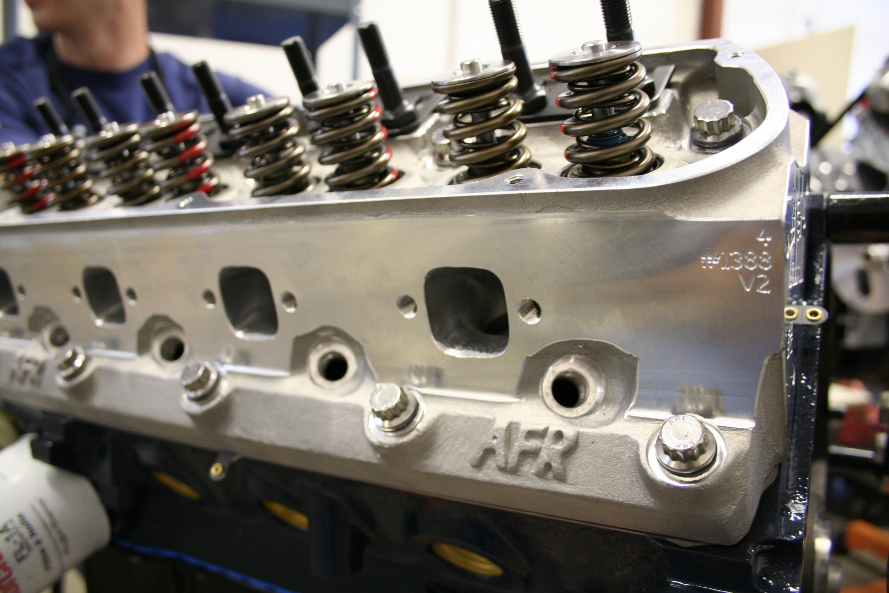
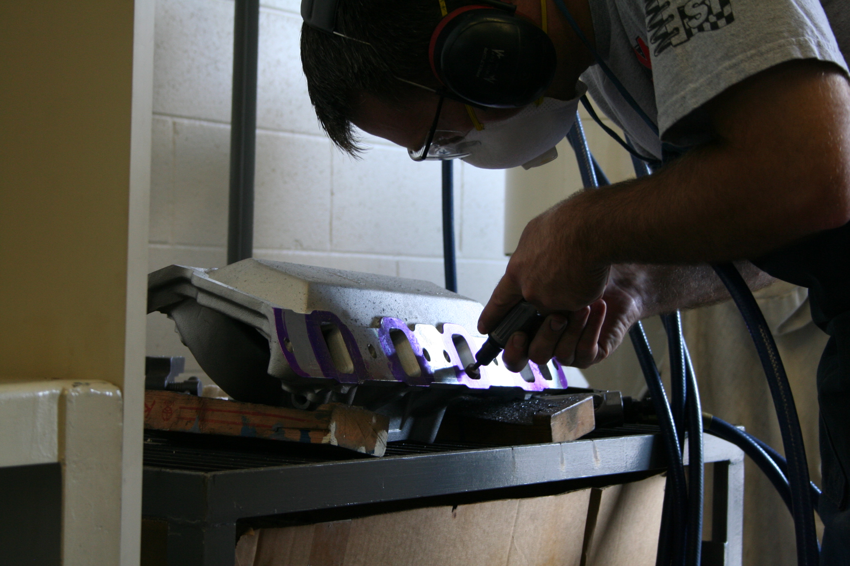
reassembled and installed. Also, my AFR 185 heads showed
up, as well as the RPM Air-Gap intake manifold and hydraulic
lifters. The intake is going to be port matched to the
heads (along with the gaskets), then off to be powder coated to
match some other engine parts.
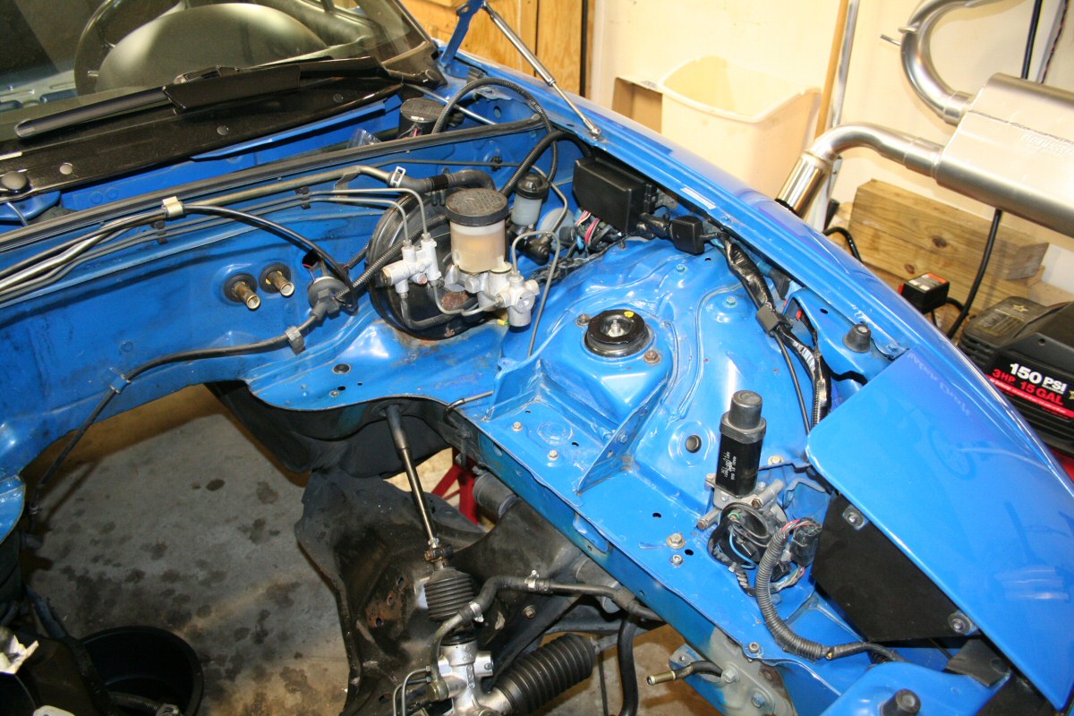
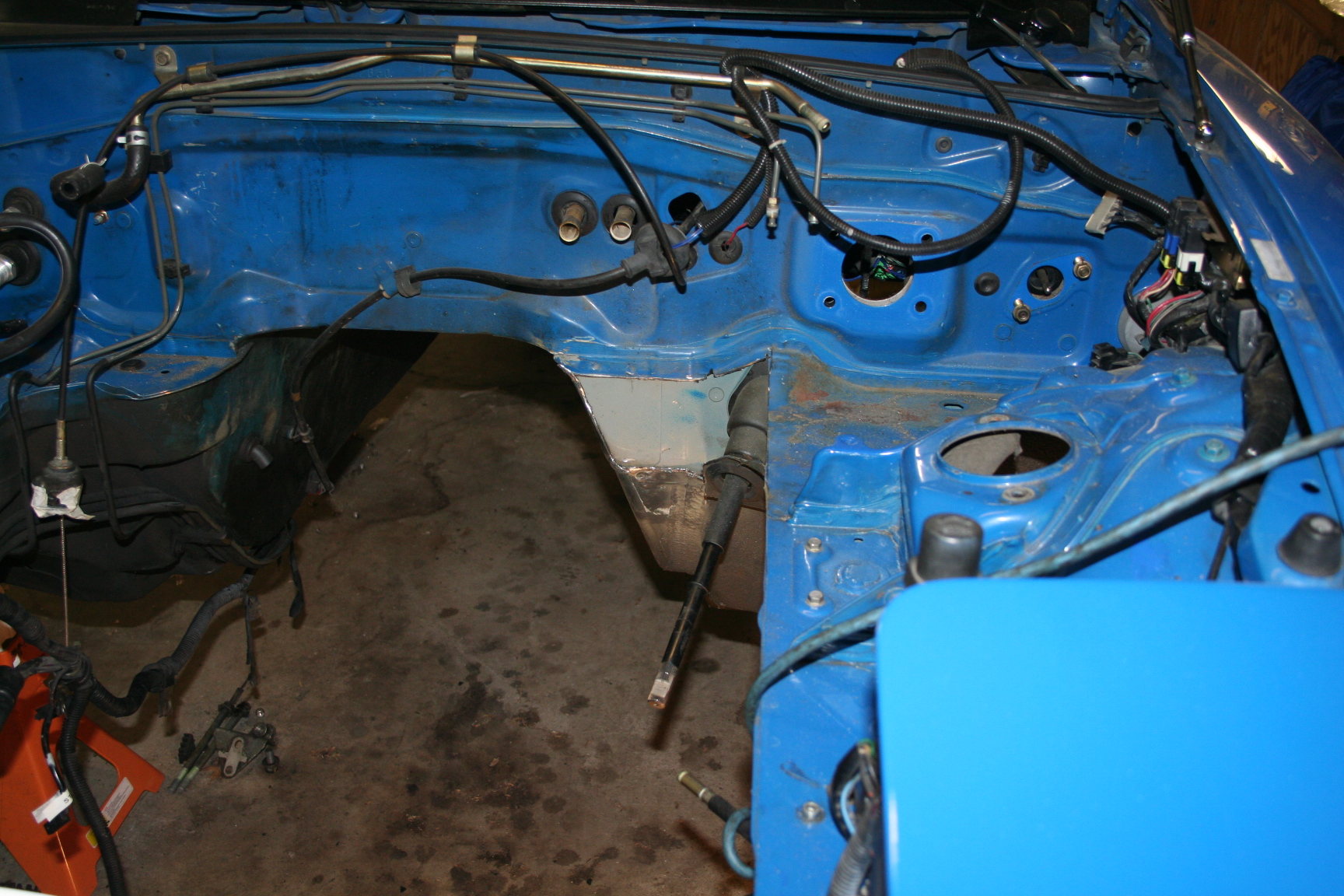
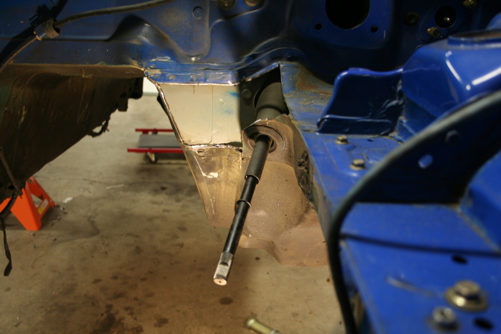
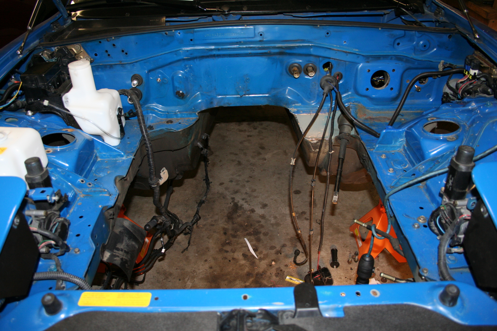
8/31/08 Today I
started on cutting out the "corners" in the engine bay
needed for clearance. I need to weld in some metal pieces
and start on the passenger side as well. I also started
clearing out some lines and such on the firewall to clean things
up and likely a repaint. The flash in the pictures make it
look worse than it is, but I'm getting closer to the point where
a repaint wouldn't be too bad.
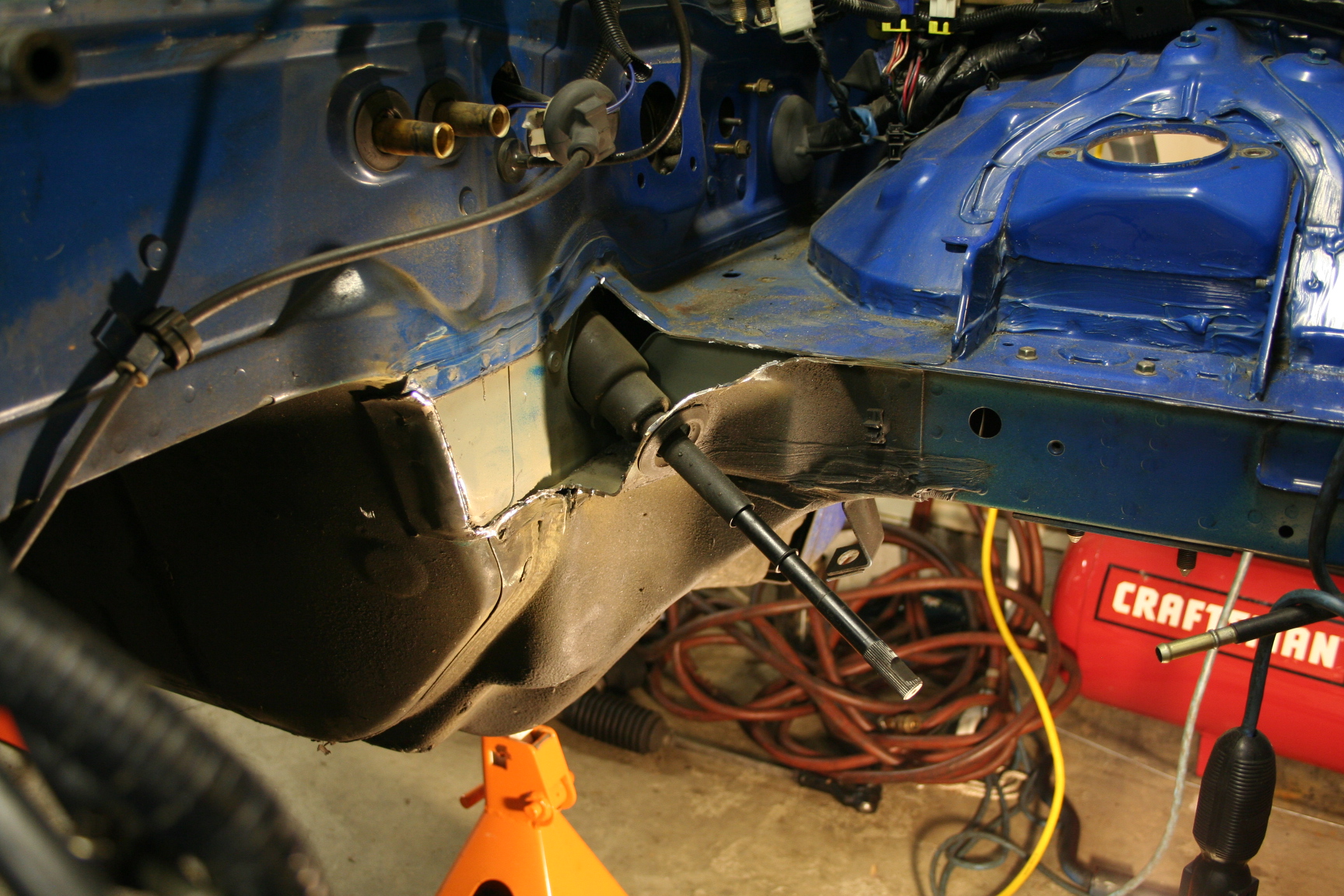
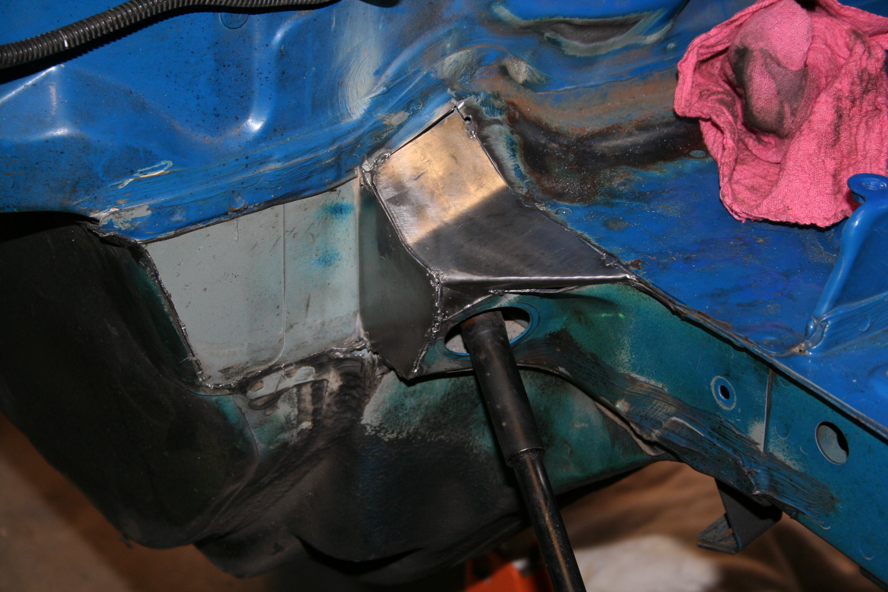
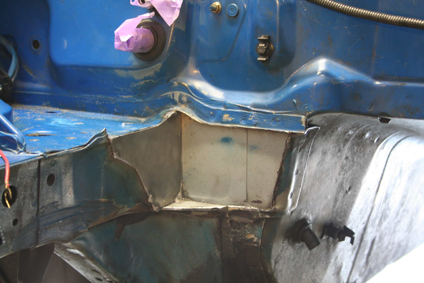
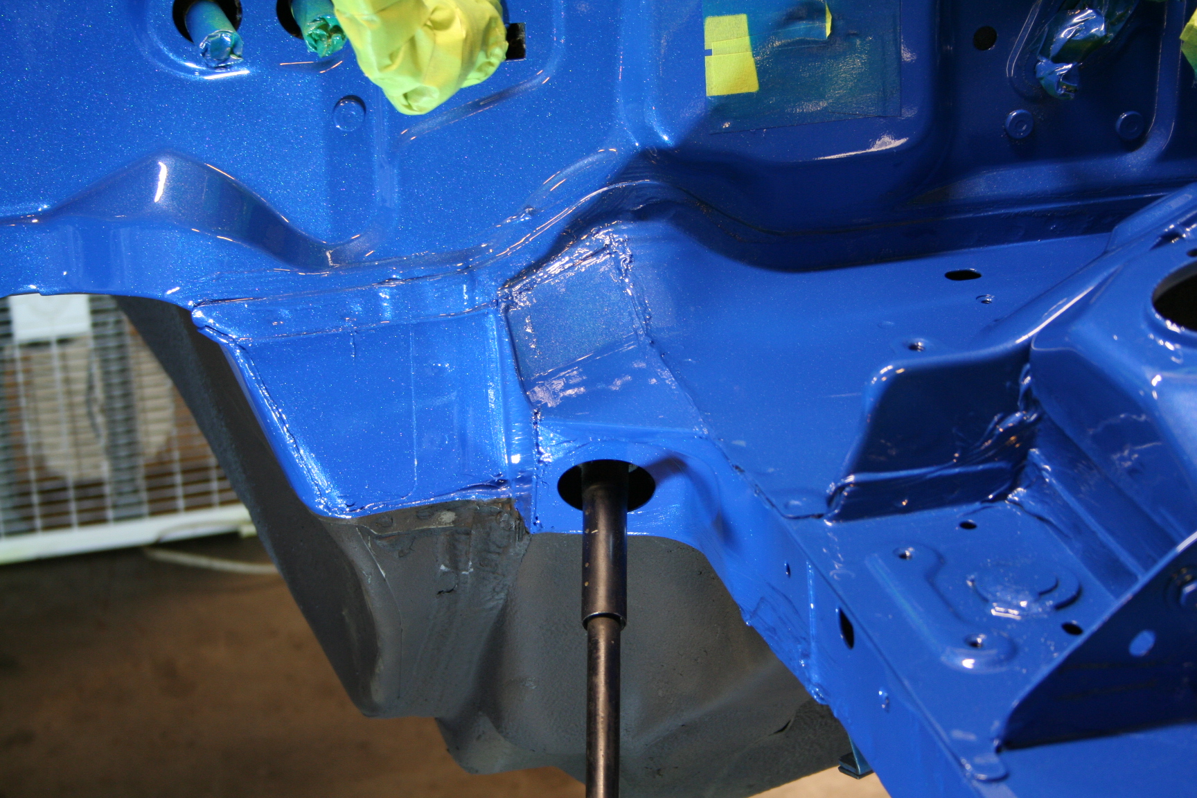
9/18/08 I
welded in some metal panels in the areas I cut. While I
continue preparing the engine bay for a re-paint, I'll apply
some seem sealer to the areas that I didn't weld (I'm not a
great welder and didn't want to hose things up too much).
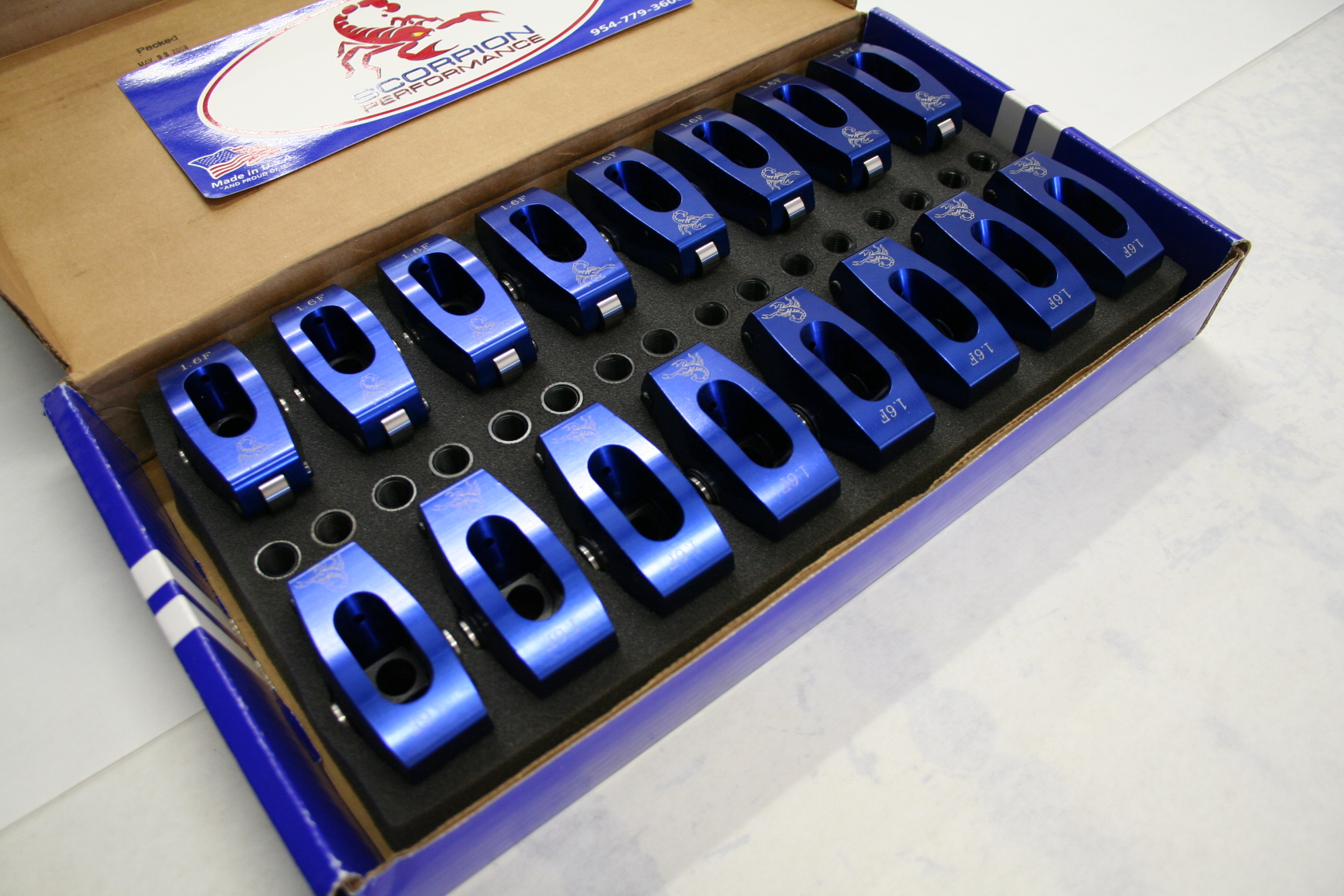
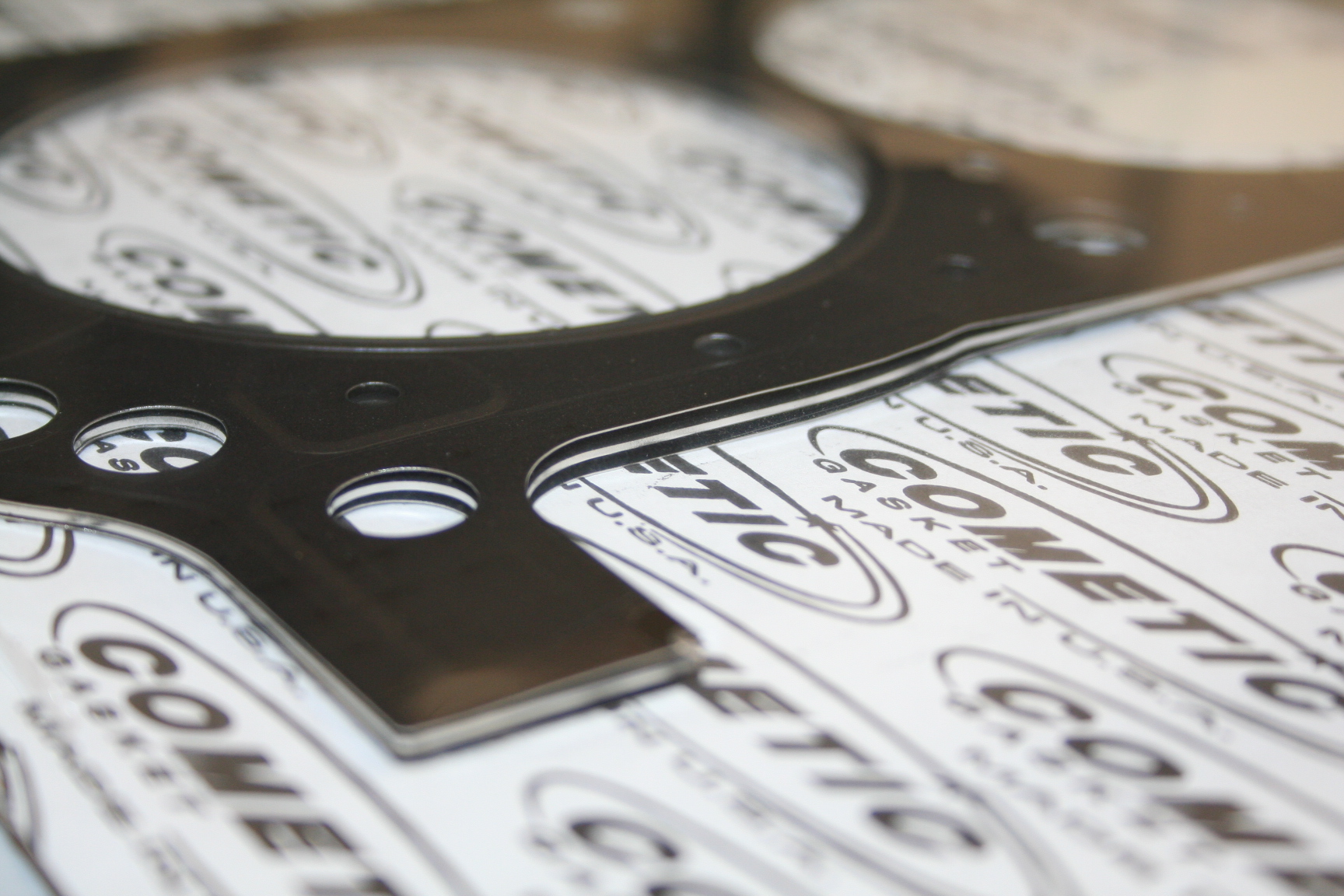
A few more things progressed with the engine at Kennedy
Performance. The Scorpion rocker arms and Cometic Multi-Layer Steel head
gaskets have arrived. Optimal pushrod lengths have been
measured and ordered. The intake manifold has been port
matched to the heads and sent off to the local powder
coater. Valve covers have also arrived.
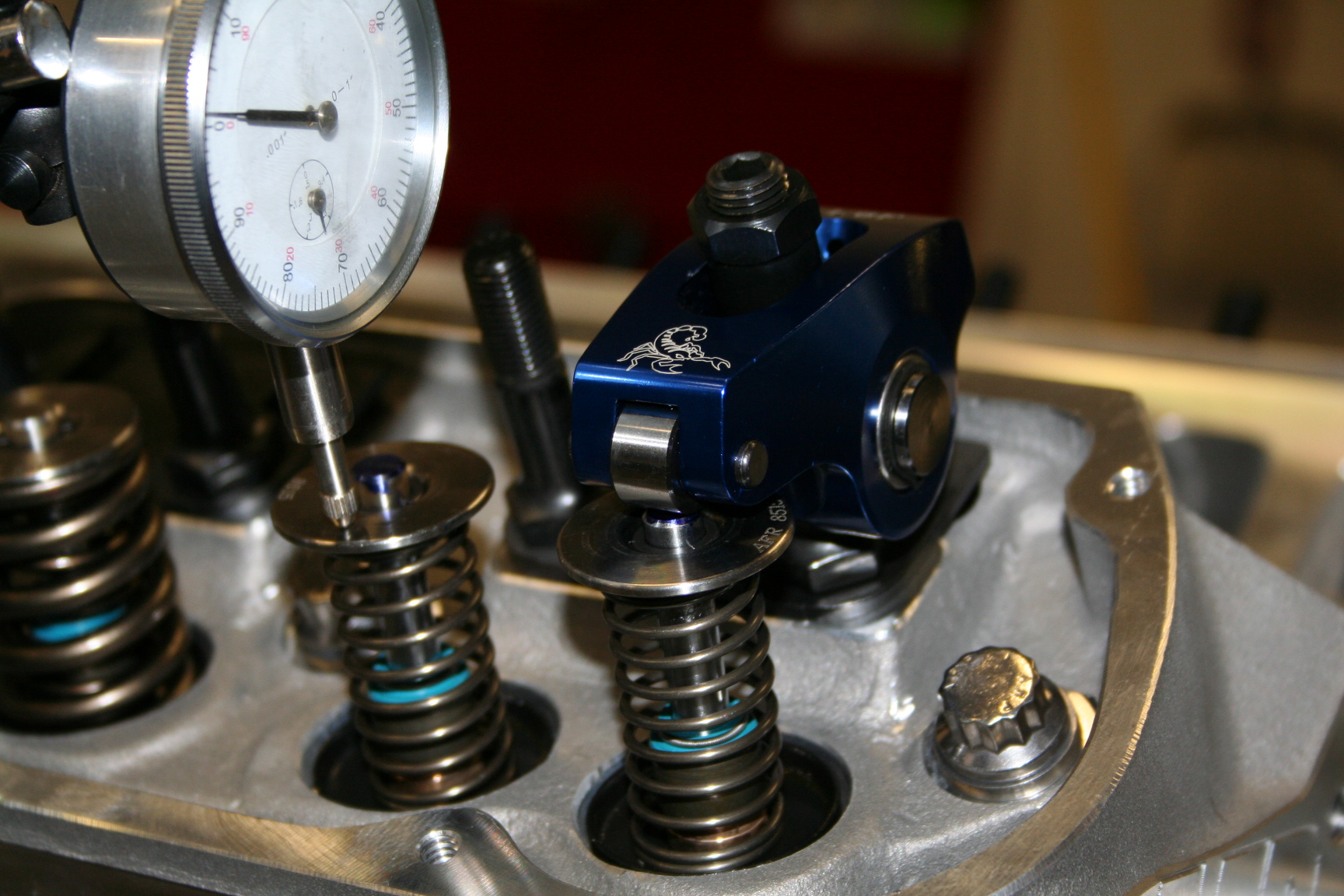
9/26/08
Pushrods have arrived and are now installed along with rocker
arms. Valve covers installed. The powder coating job
on the intake manifold looked great... until it was mounted on
the engine. Something went wrong with the prep work,
application or possibly the powder quality itself. As soon
as the bolts were tightened, the coating began to chip. It
even flaked at the edges where the intake meets the heads.
I sent it back for a strip and recoat. Hopefully it will
be better the next time around.
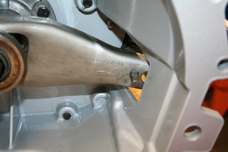
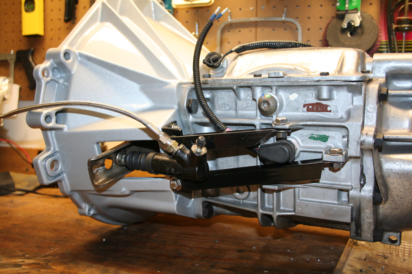
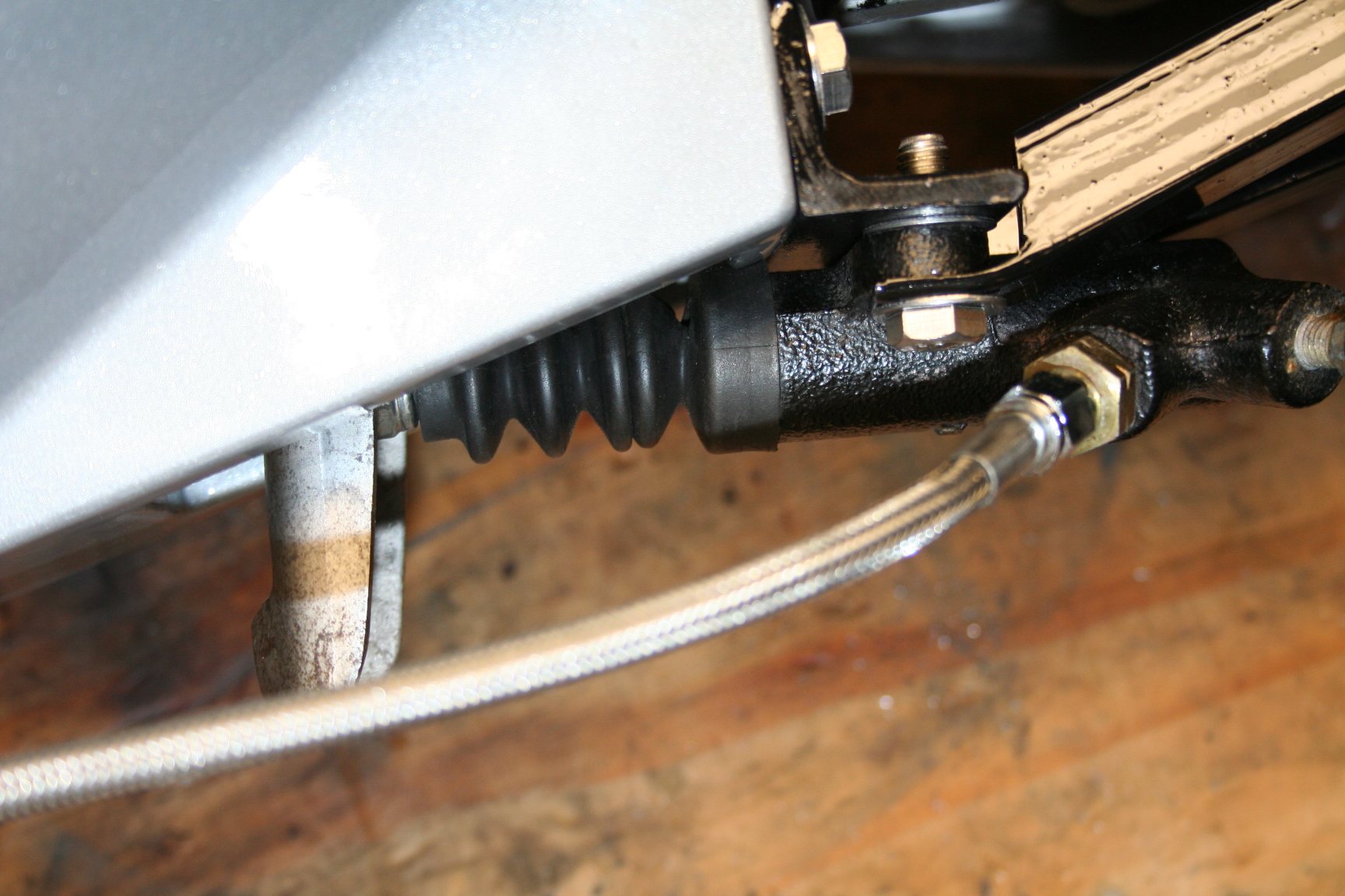
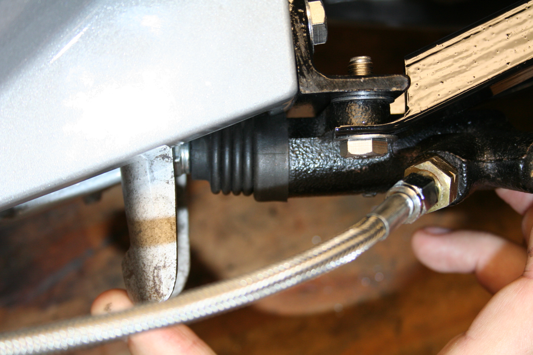
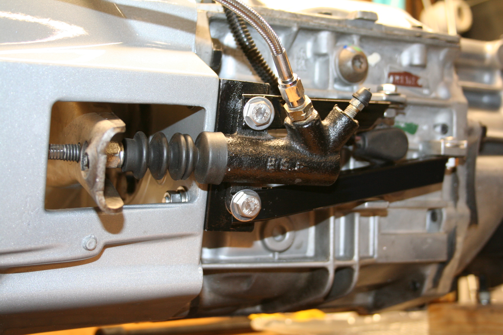
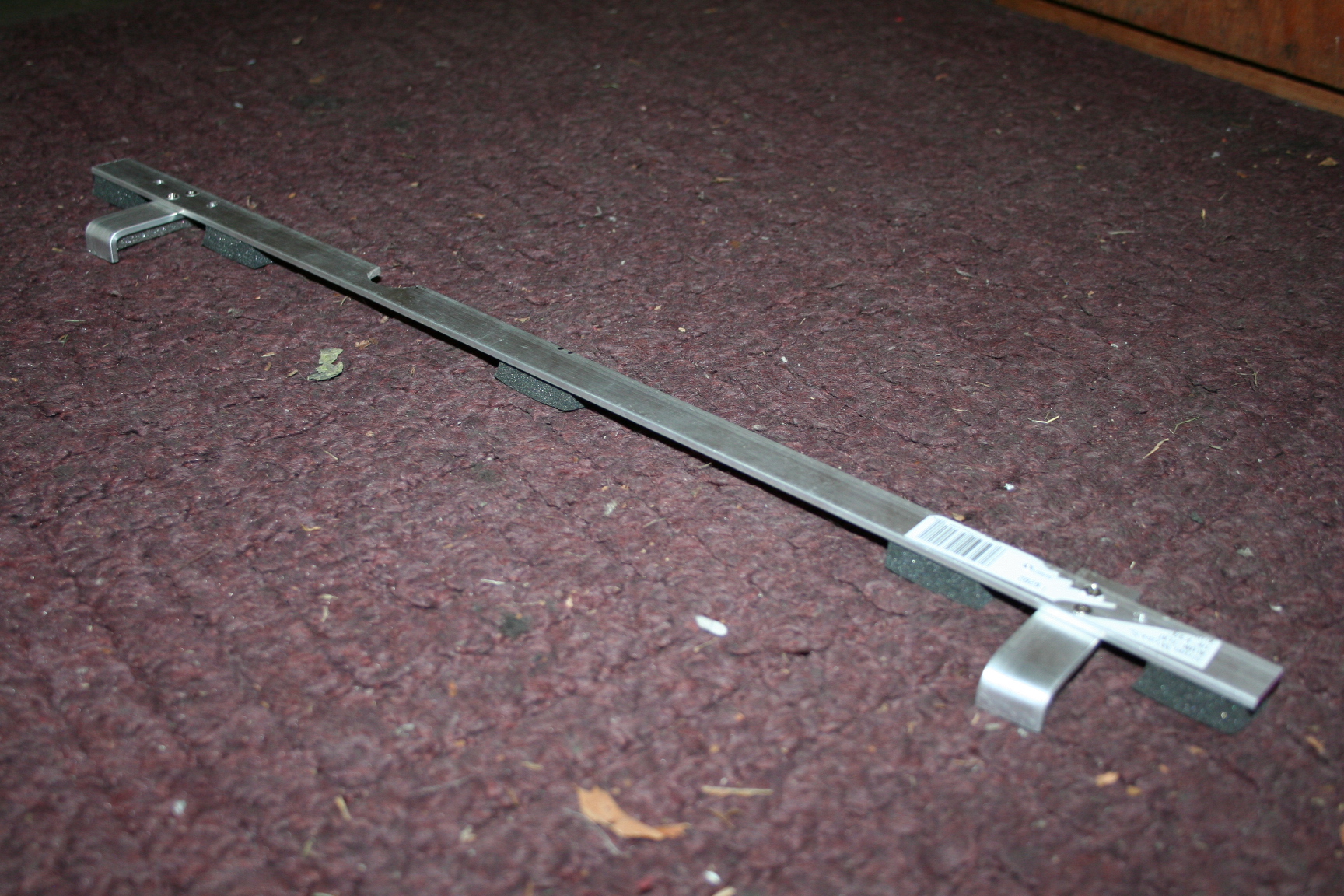
Shifting over to the
clutch, I test fitted the slave cylinder, fork and adapter
bracket for the slave. In an effort to improve the clutch
performance, I have reinforced the mounting bracket with two
horizontal brackets made of 3/4" square steel tubing
mounted to some available bosses on the tranny. Also, the
mounting bracket was bent a bit to point the slave just in the
bell housing opening. This was to improve the direction of
the slave cylinder pushrod and to give more throw to the fork
for the same displacement of the slave piston. This
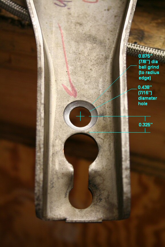
required drilling a new hole (and radius the edges) for the push
rod and pivot to meet against the fork. Hole dimensions...
center point is 0.325" above edge of "other"
hole, hole is 7/16" diameter, and edges where chamfered
(radius) using a 7/8" ball shaped grinder. Since the
metal is very hard, I had a machine shop do the work. The
dimensions above are what I used except I centered a hair higher
at 0.350". I think 0.325" would be better.
9/27/08 I met a
fellow Ford 302 converted Miata owner over the weekend and had a
great discussion on a lot of things involving the
conversion. He has done quite a great job on his
conversion. The donor engine/tranny came from a '95
Mustang so he used the SN95 accessory brackets including using
the AC compressor in the normal location. This is the
first I've seen that did this, and he confirmed there is an
interference with the frame. His solution was to make a
minor mod to the frame and it turned out very well. I
might go this route if not the smog pump location.
The color of this car is a
very deep red. It looks great; the pictures don't do it
justice. Here's a video of his car.
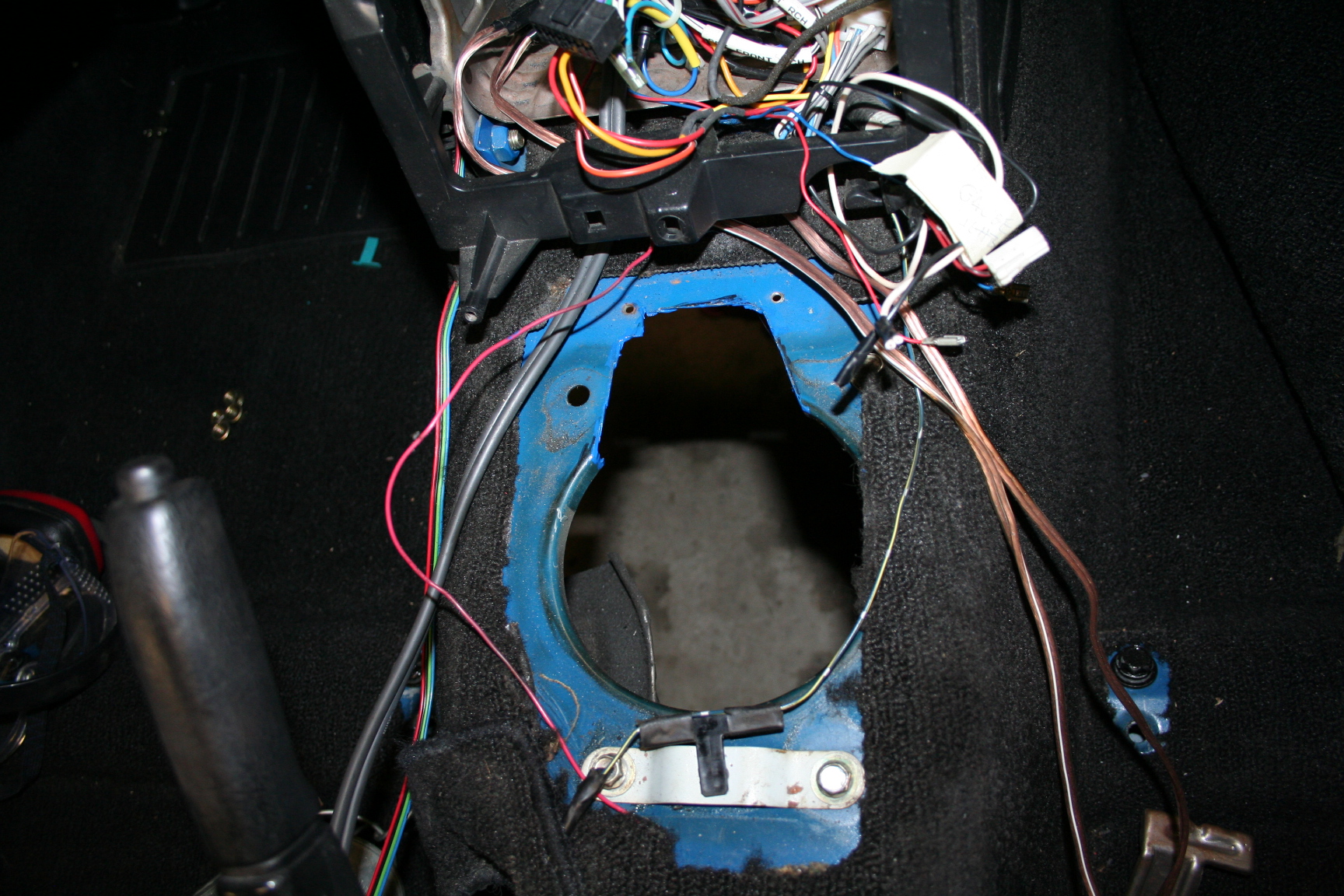
10/02/08 Working on the engine
bay a bit. I've decided to repaint the bay. Lots of
sanding of the old paint and removing parts and harnesses. I
went ahead and repainted some of the undercoating that was near
the new welded in panels and tranny tunnel. The hole in the
tranny tunnel for the shifter was modified to accept the shifter
adapter. The radio bezel was also cut some for clearance.
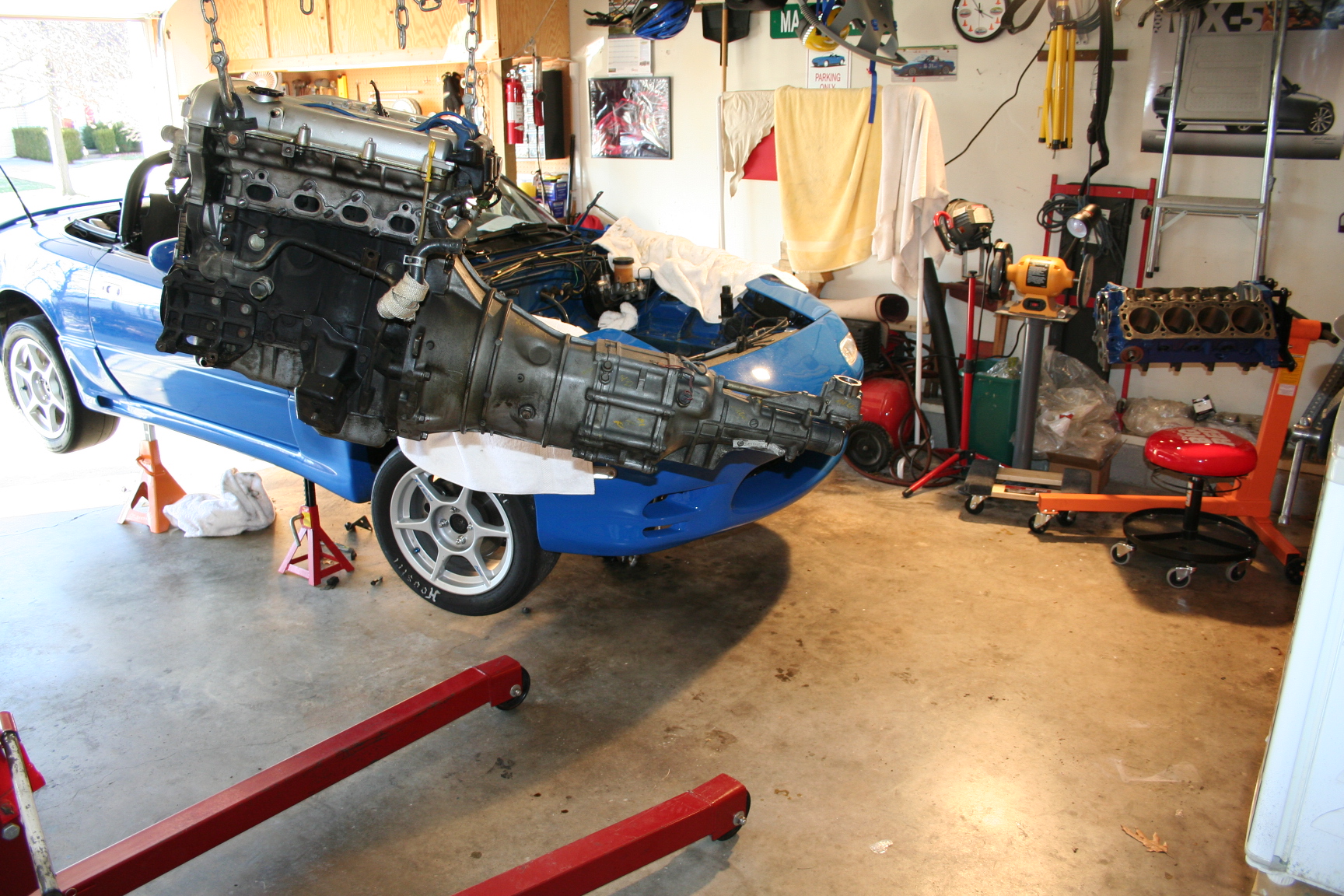
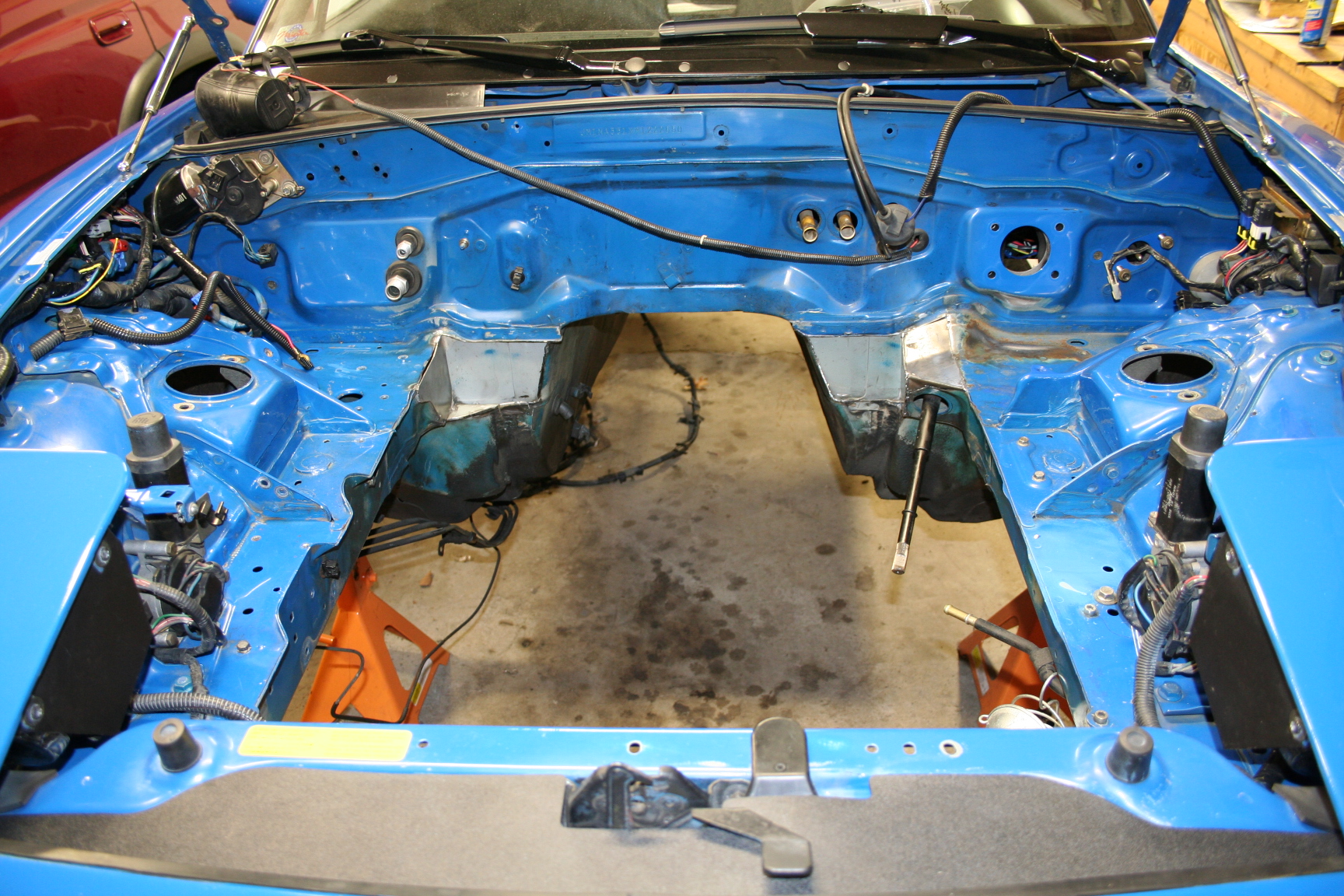
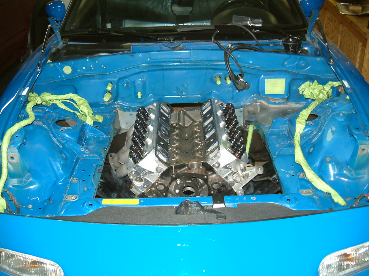
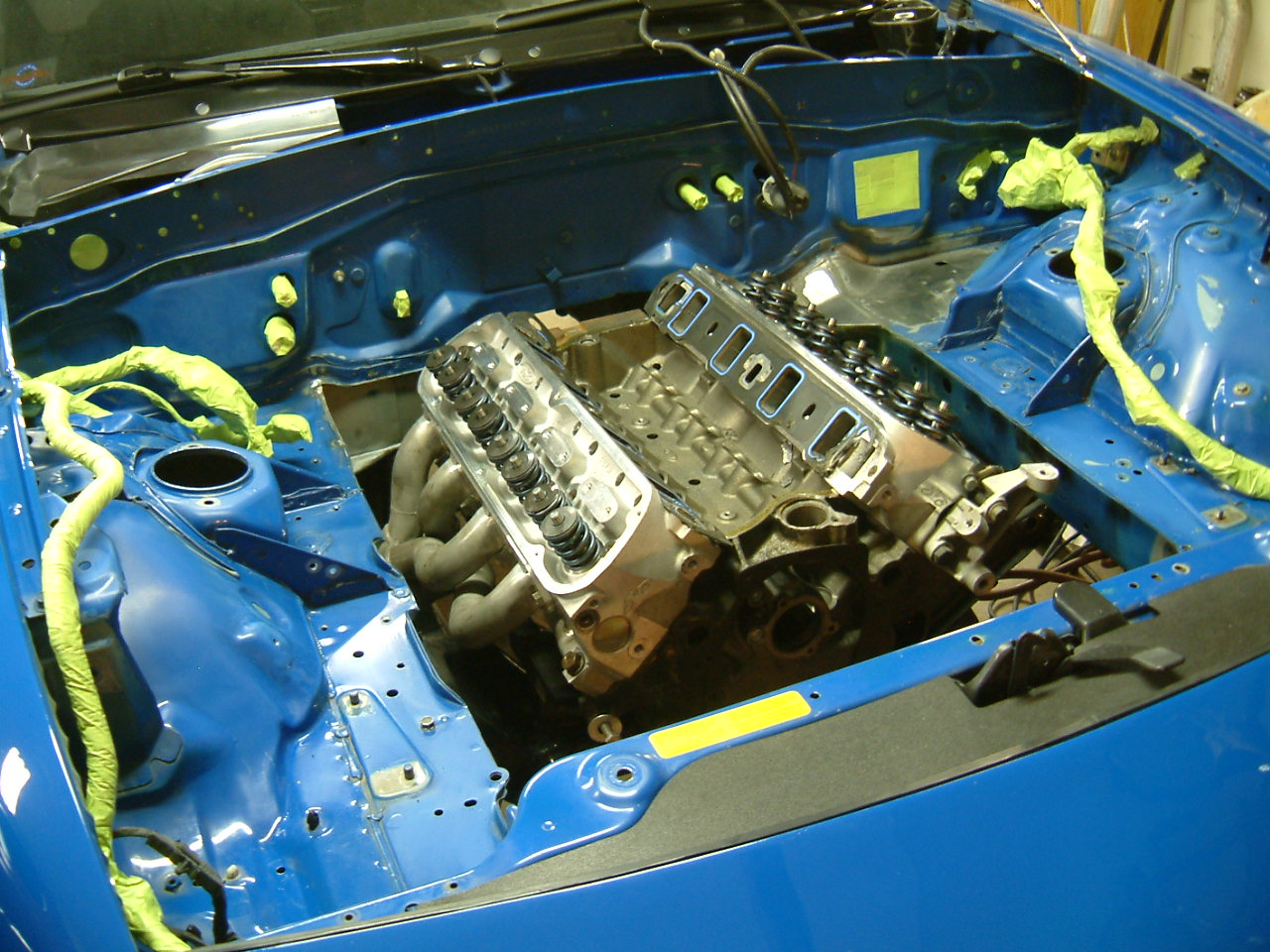
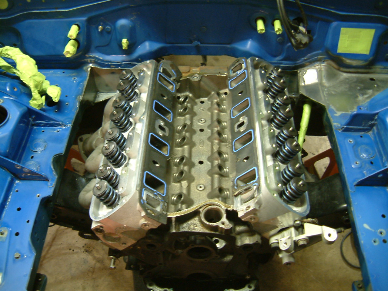
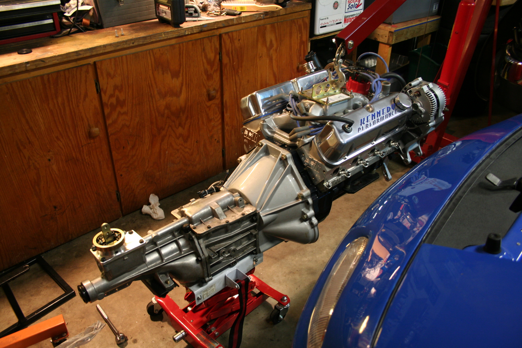
10/05/08 Today I took Nigel's
loaner engine block and heads and mounted them up with the
subframe into position. I wanted to check clearances before
I paint the engine bay, and also get a look at where the headers
will fall into position. I gotta say, seeing the loaner
block in place looked pretty cool. I can't wait to get this
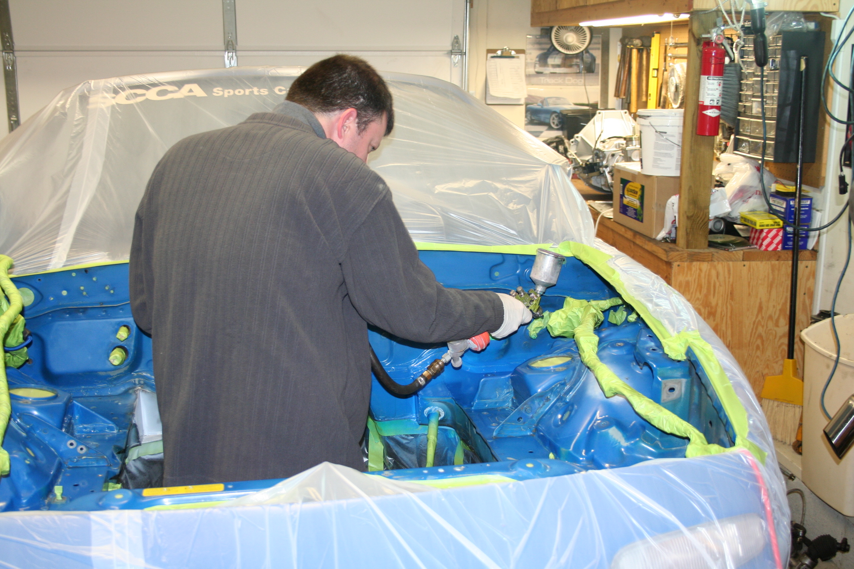
conversion done. Oh, the green stuff is taped up harnesses
and such that I don't want to get paint on. I'm almost ready
for the paint.
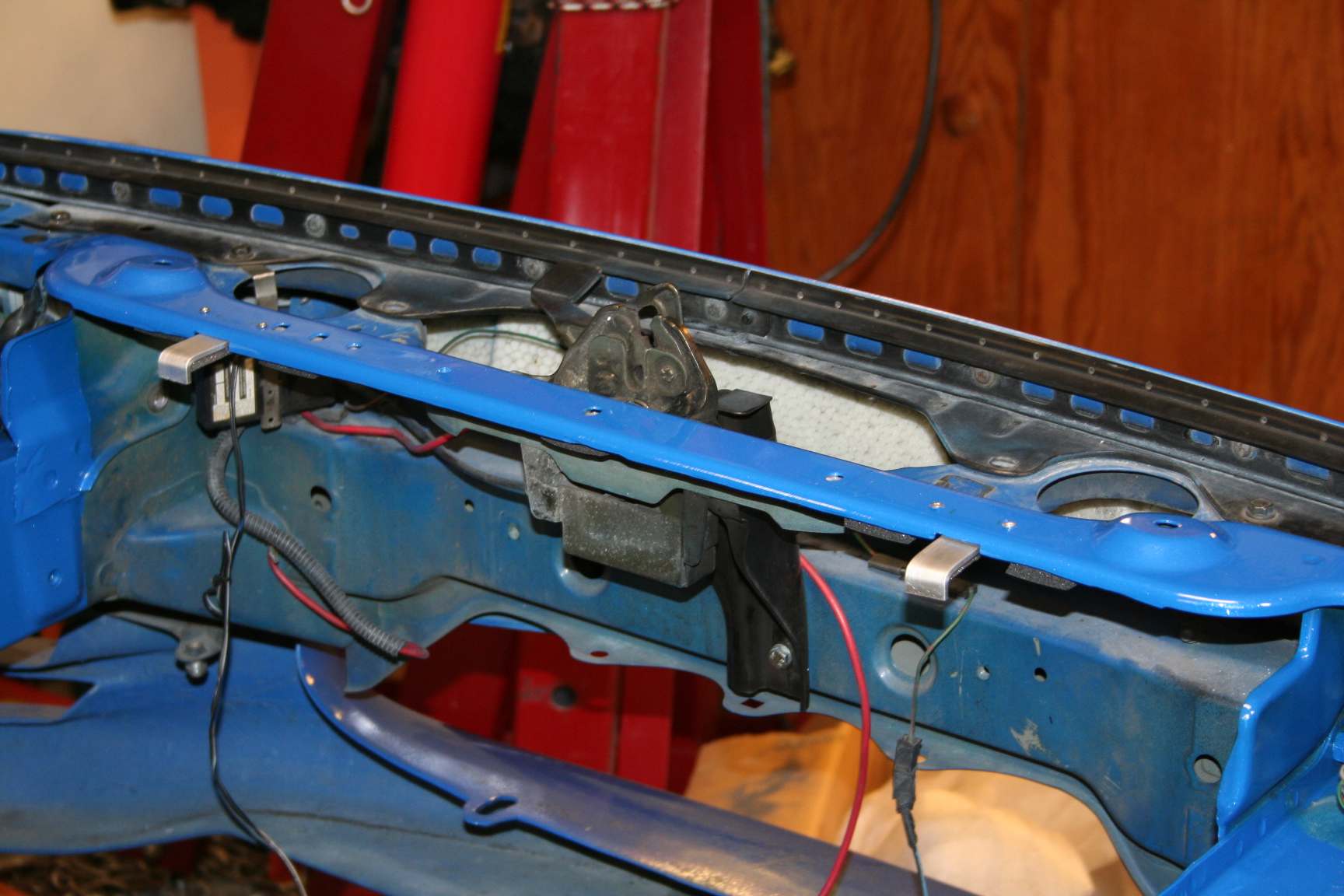
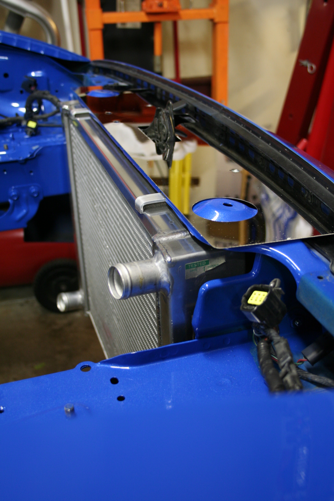
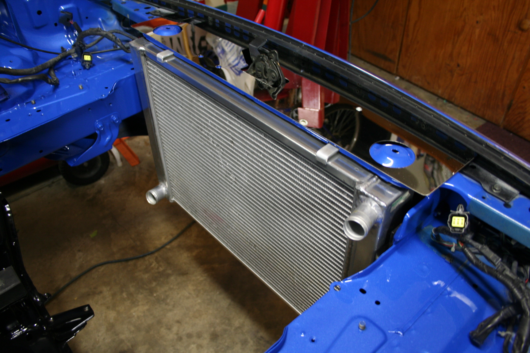
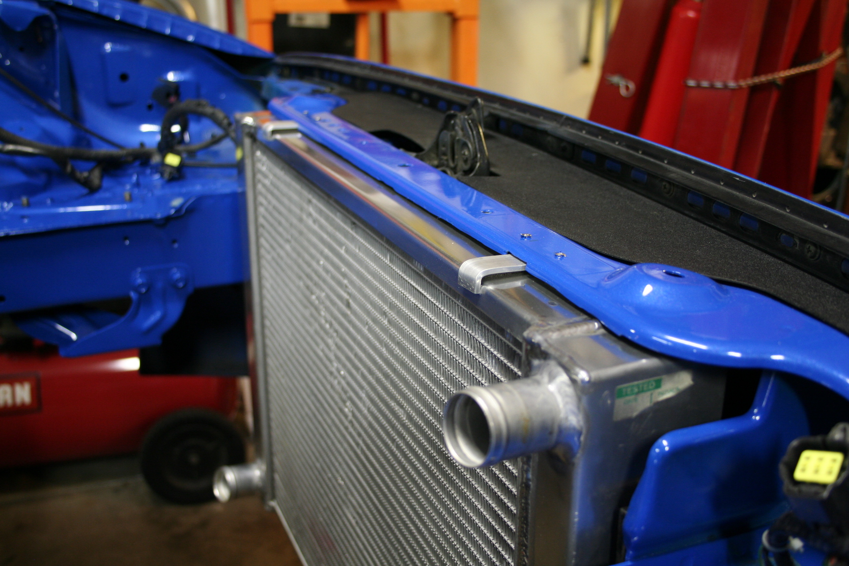
11/02/08 I test fitted
the radiator. Instead of bending up the edge of the upper
radiator frame (per the kit instructions), I decided to trim off
the piece and make a bracket to secure the top of the
radiator. I'll also cover it all up with a polished upper
radiator cover or maybe keep the black plastic cover I had before
the conversion..
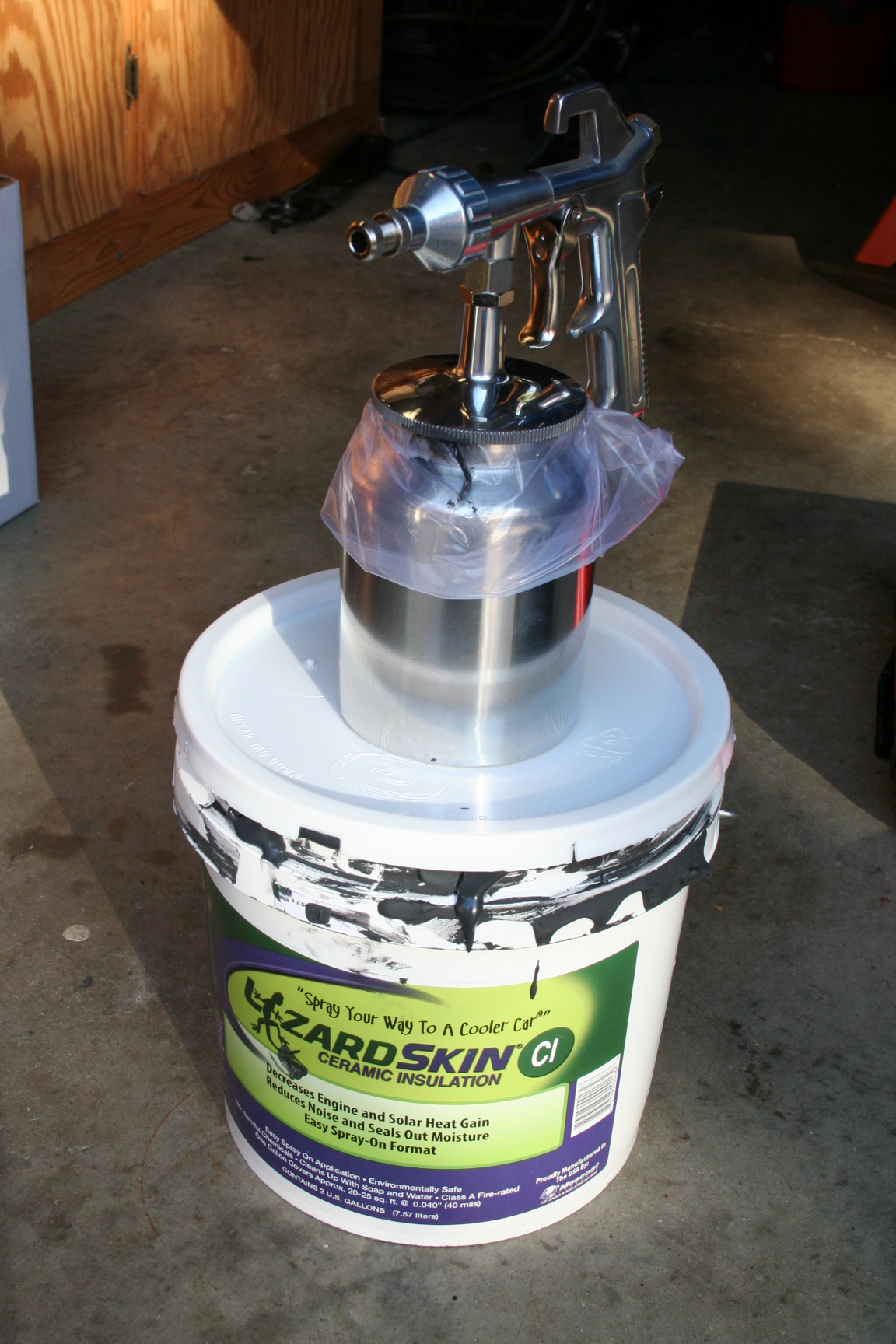
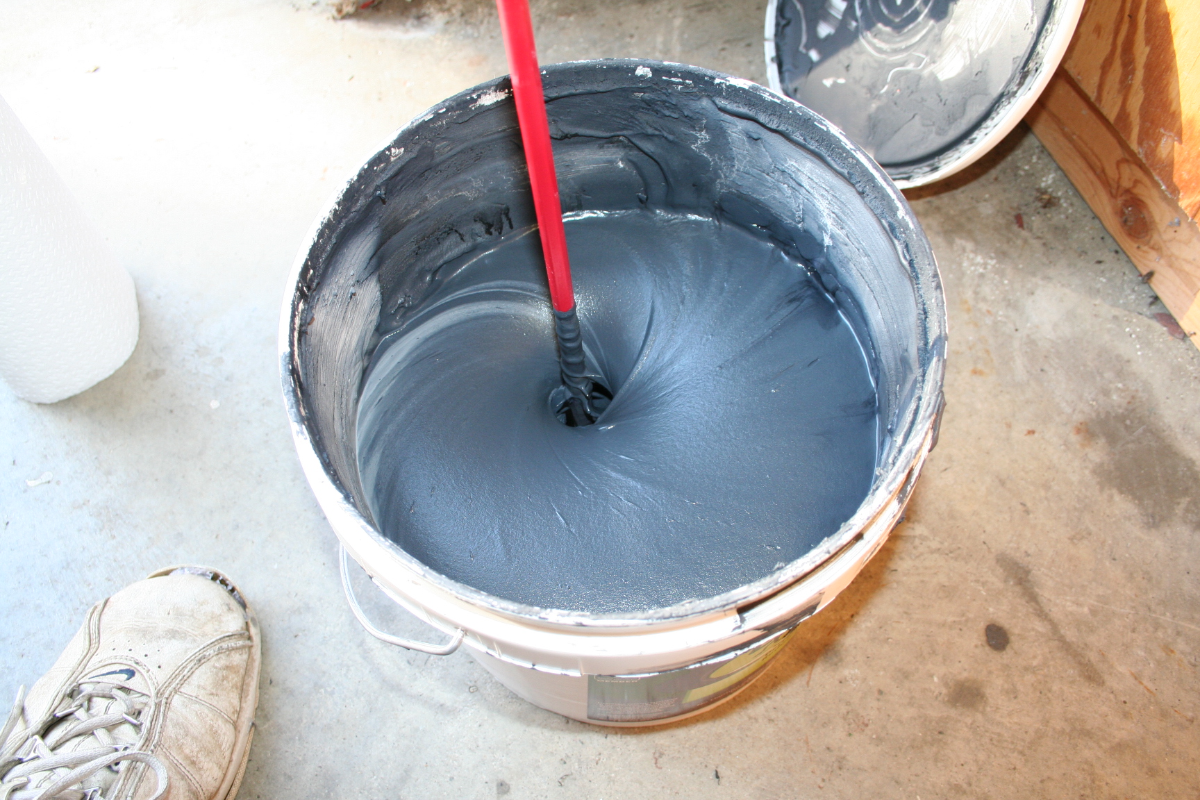
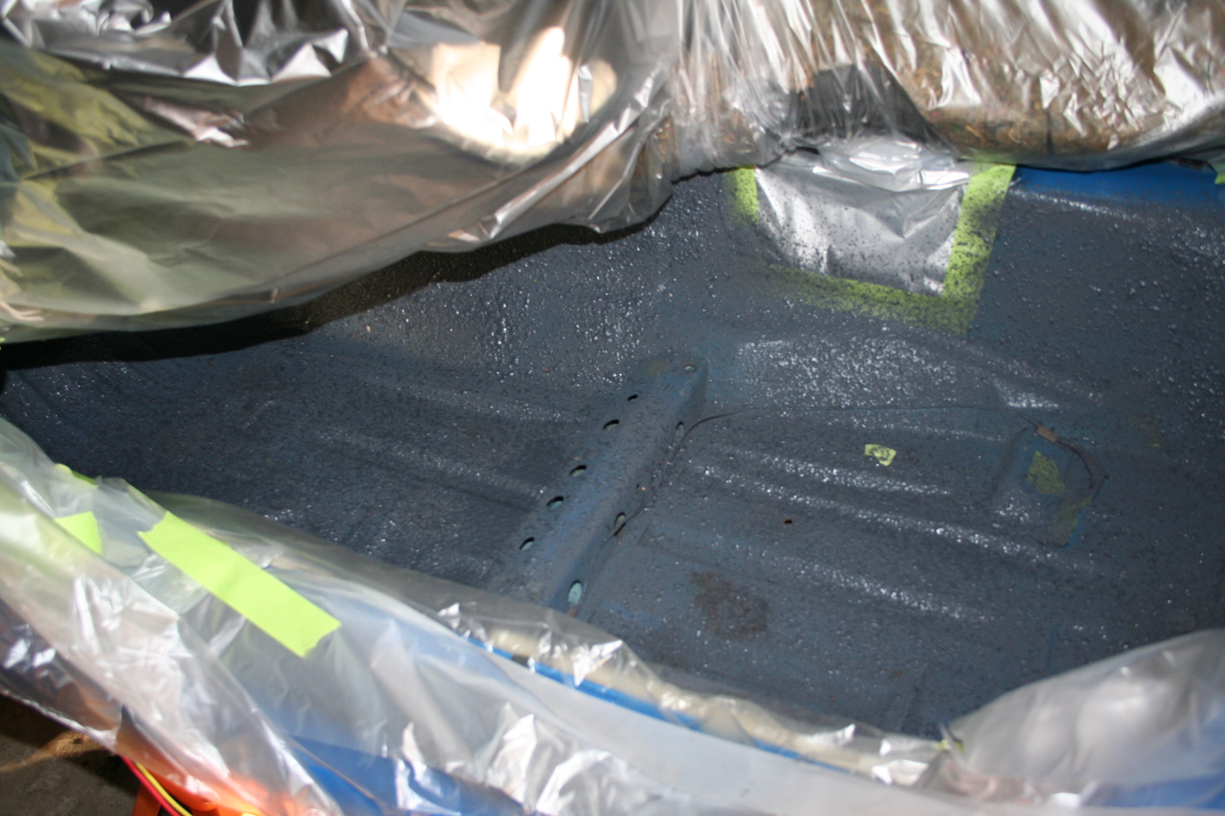
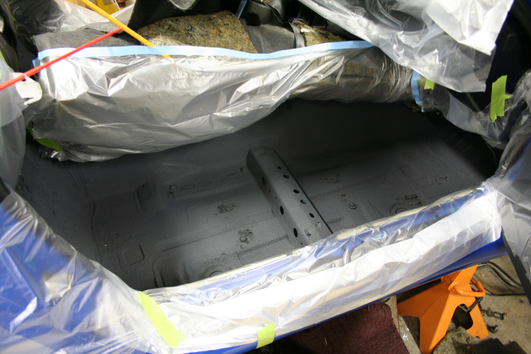
11/10/08 To minimize
the heat transmitting into the cabin from the engine and exhaust,
and to also suppress a bit of noise, I was turned on to using
spray on ceramic insulation called Lizard Skin. This stuff
is as thick as brownie batter but if you use their spray gun and
enough pressure, it does a good job of atomizing and
spraying. I chose to spray the cabin floor pan by pulling up
the carpet as much as I could, as well as the trunk floor.
This stuff is messy, but I think it went on pretty well after
working with it a bit. It would have been nice to pull the
dash and hit the entire firewall but I think it will still be
effective.
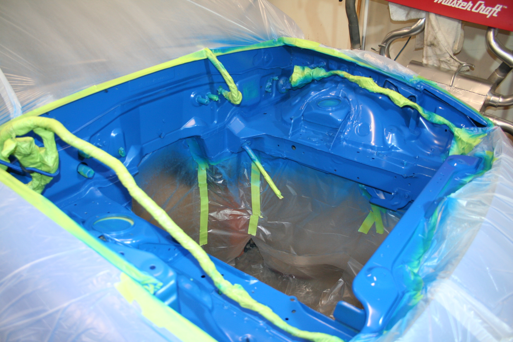
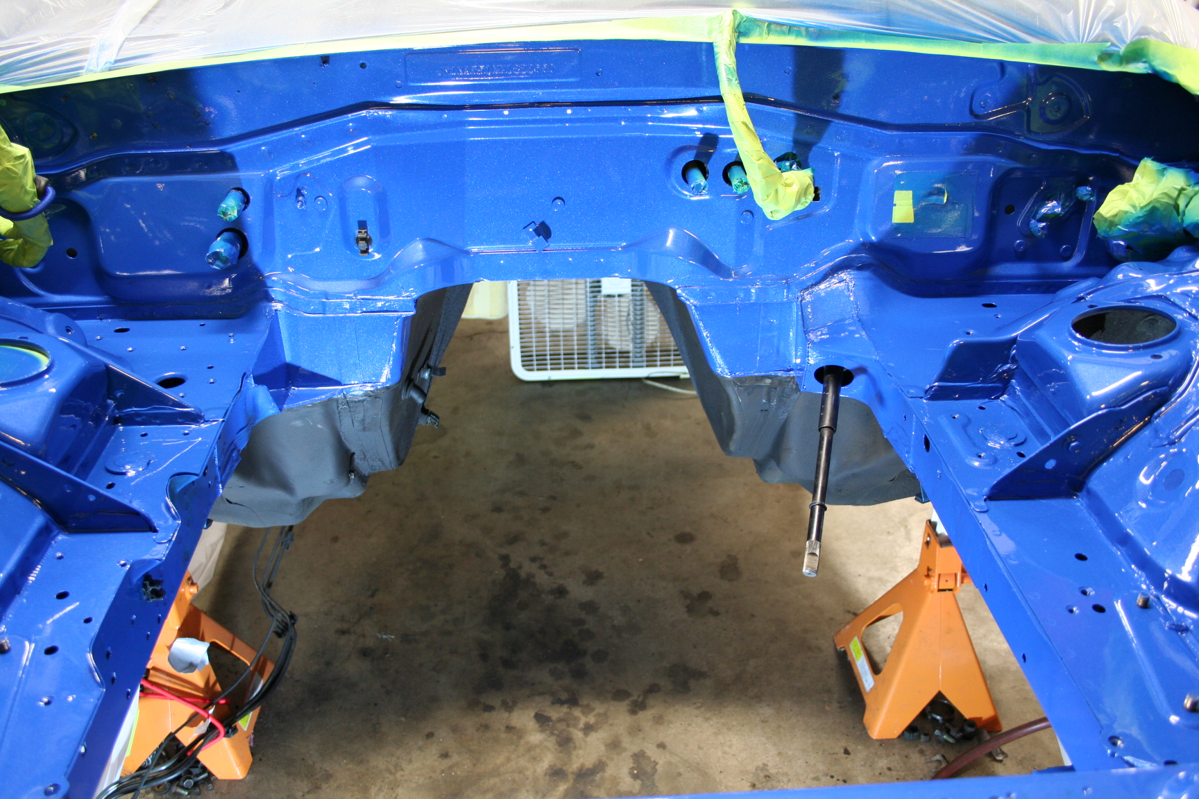
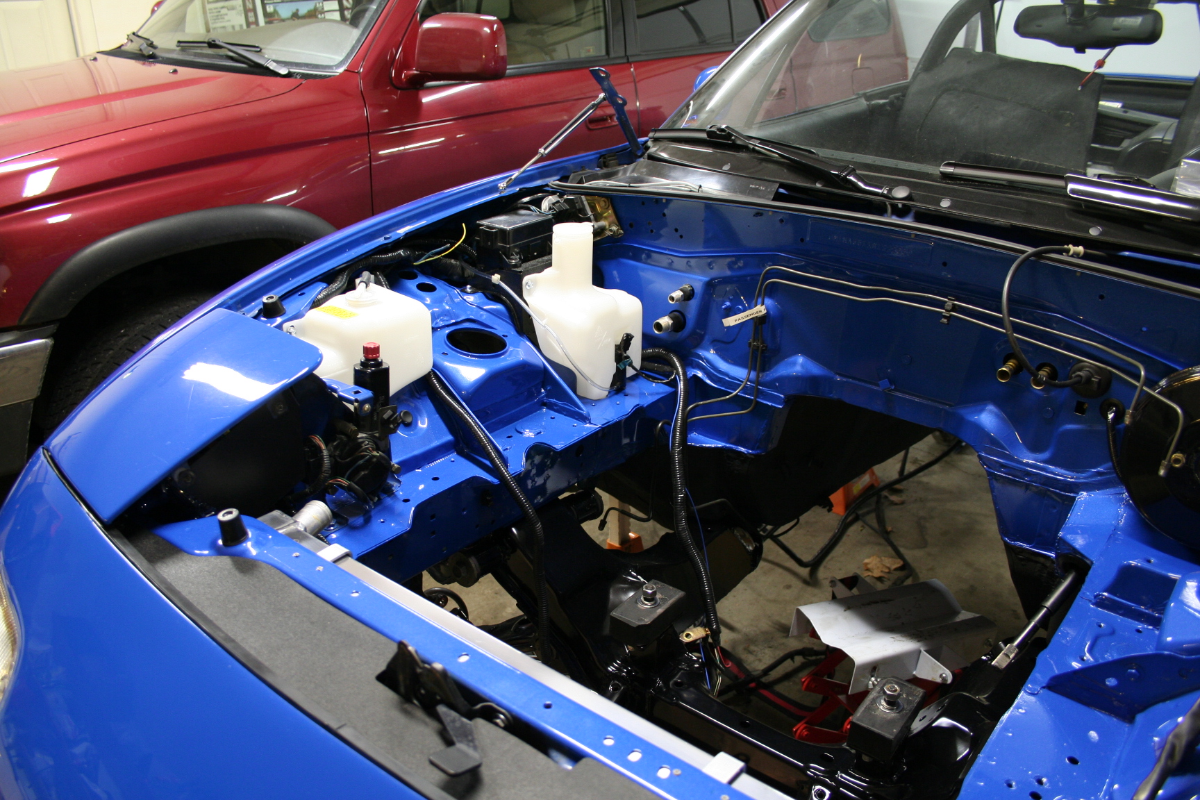
11/17/08 The engine
bay was painted today. Steve Kelley came over to help with
the final prep and spray in my garage. As usual, he did an
outstanding job. The pictures really do not do it
justice. Steve mixed in some blue pearl in the clear coat
much like the pearl in the exterior paint job he did for me.
I think it turned out great and I can't wait to start putting
things back into the engine bay.
1/02/09 At this point,
I have a lot of irons in the fire. The engine is mostly
done, but there are a few things left to button up. Without
too many details for now, the carburetor is ready to go on, the
distributor is almost ready to go on, the 94-95 Mustang engine
accessories had a slight interference with my valve covers and a
solution is being sorted out, all of the accessory bolts are being
identified and sourced through ARP, the PS pump bolts are
interfering with the PS pump pulley, and the spacer between the ATI
balancer and the crank pulley needs to be modified once the
thickness is determined. In the mean time, I have been
working on sorting out some electrical things including swapping
out the battery to starter wire from the factory 4 (or maybe 6)
gauge to a 2 gauge wire, extending the oil pressure sensor wire
over to the driver side, rewiring the cooling fan circuit to
support more current through the factory fuse and relay, and a few
other small things. Modifications for the radiator mounting
is complete, however it is removed until the engine is
installed. The fuel system still needs to be verified that
it meets requirements and I hope to perform some flow/pressure
tests soon.
The next big
checkpoint is to have the engine complete and running for the
first time on an engine dyno. I have tentatively scheduled a
dyno session at the end of January so hopefully I'll have a
running engine within a few weeks.
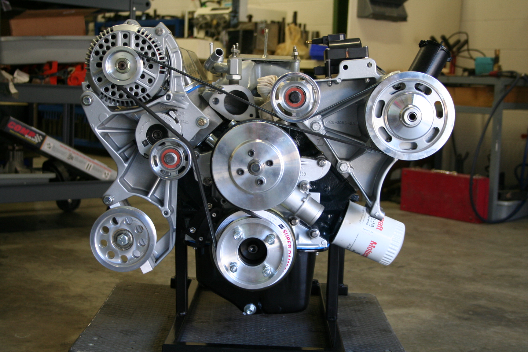
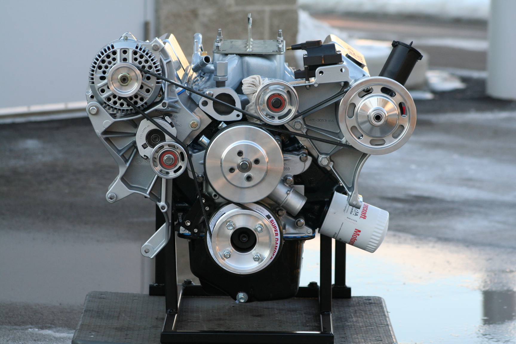
1/05/09 I made a
little more progress on sorting out the accessory interference
issue and test fitted the coolant pipes above the intake manifold and
fitted the carb.
2/06/09 Well, the
engine isn't quite done yet, nor is the engine dyno that I want to
use at SR Racing quite ready. That's ok; it will be done
eventually.
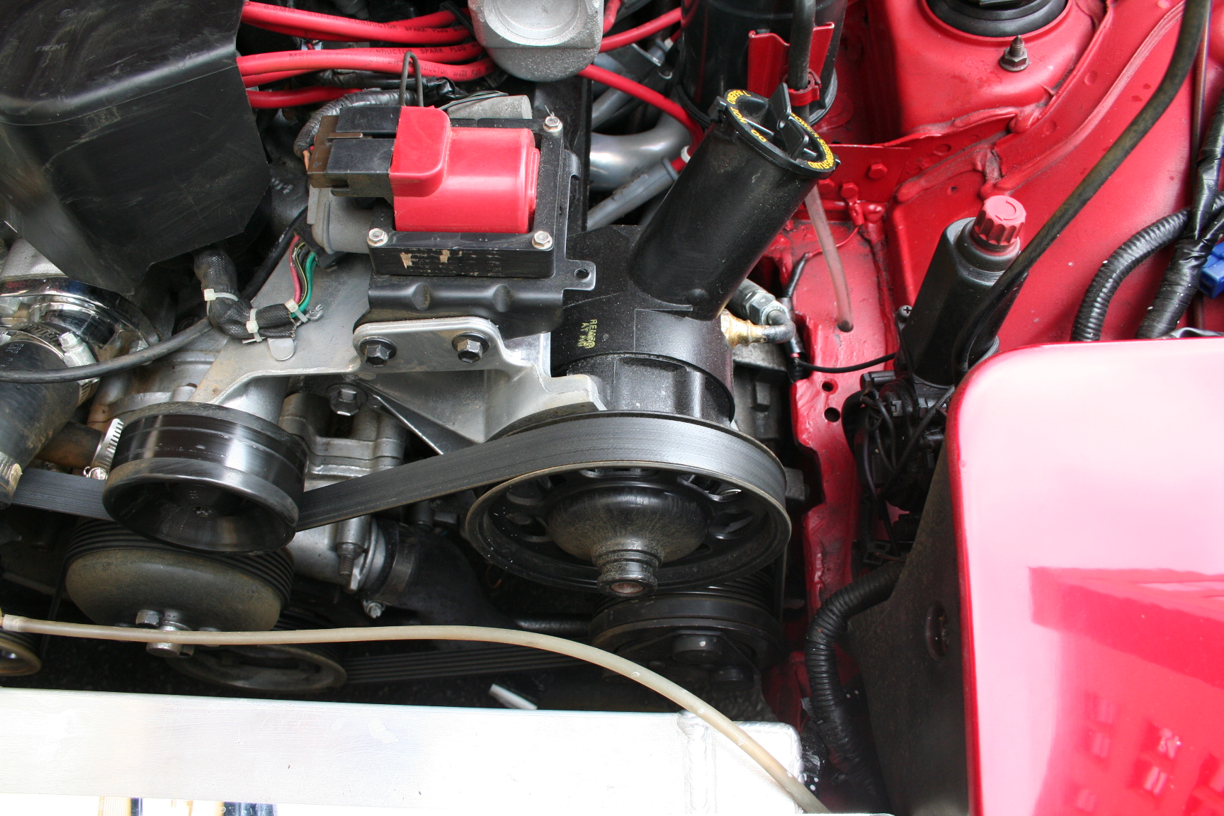
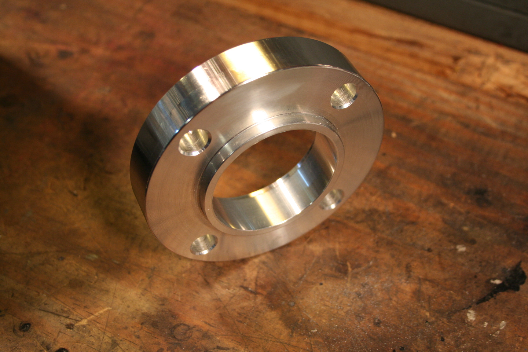
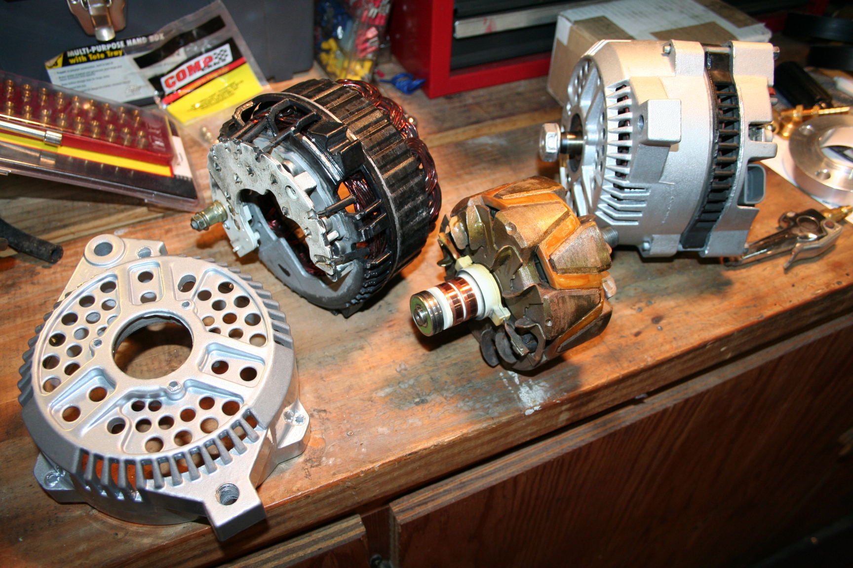
A few more things
have progressed:
The solution to the
alternator interference with the valve cover was fairly
easy. I found some 1/8" thick washers at a local
spring/suspension shop that I used to space out the accessory
brackets. This moved all of the pulleys out except for the
water pump and crankshaft pulley. The water pump pulley is
so wide that I didn't need to do anything with it. The
crankshaft pulley was going to require a special spacer anyway so
I added in the thickness of the washers. I bought a spacer
from Ford Racing and had it turned down to the thickness I
needed. I also had to grind a small area of the back of the
alternator near the back bearing housing for additional
clearance. I got a little picky again and took it apart to
have both housings powder coated.
The power steering
pump pulley was pressed on and crankshaft pulley and spacer were
mounted temporarily while I continue to wait for some ARP bolts to
arrive. I also realized that there really isn't a need for
the smog pump bypass pulley in my case and figured out a simpler
belt path. The bypass pulley was removed. The belt I
ended up with was 81 1/8" long (K060806). I have since
then used a K060802 which is about 3/8" shorter as the other
belt ended up being just a bit short (the belt tensioner was
bottoming out).
The distributor
would have been mounted up by now, but my engine builder and carb
specialist have recommended that I have a special advance stop
bushing made that is a little bigger than the biggest one that
came w/ the dizzy. This narrows the range of ignition
advance change. If we don't need it, we can swap back to one
of the ones provided w/ the dizzy.
2/27/09 A few more
small odds and ends... water neck is on, the remaining ARP bolts
are finally swapped out, and the Lokar dipstick is in. The
larger advance stop bushing for the distributor was made, but
there is a interference with it inside of the distributor and I
need to pull the gear back off to disassemble and open up the area
with the interference. Also, the heater tubes need some
attention. I had to disassemble it when I had it powder
coated and upon reassembly, it was evident that the o-rings inside
needed replacing. I need to pick up some o-rings and reflare
the end to hold the fitting back on.
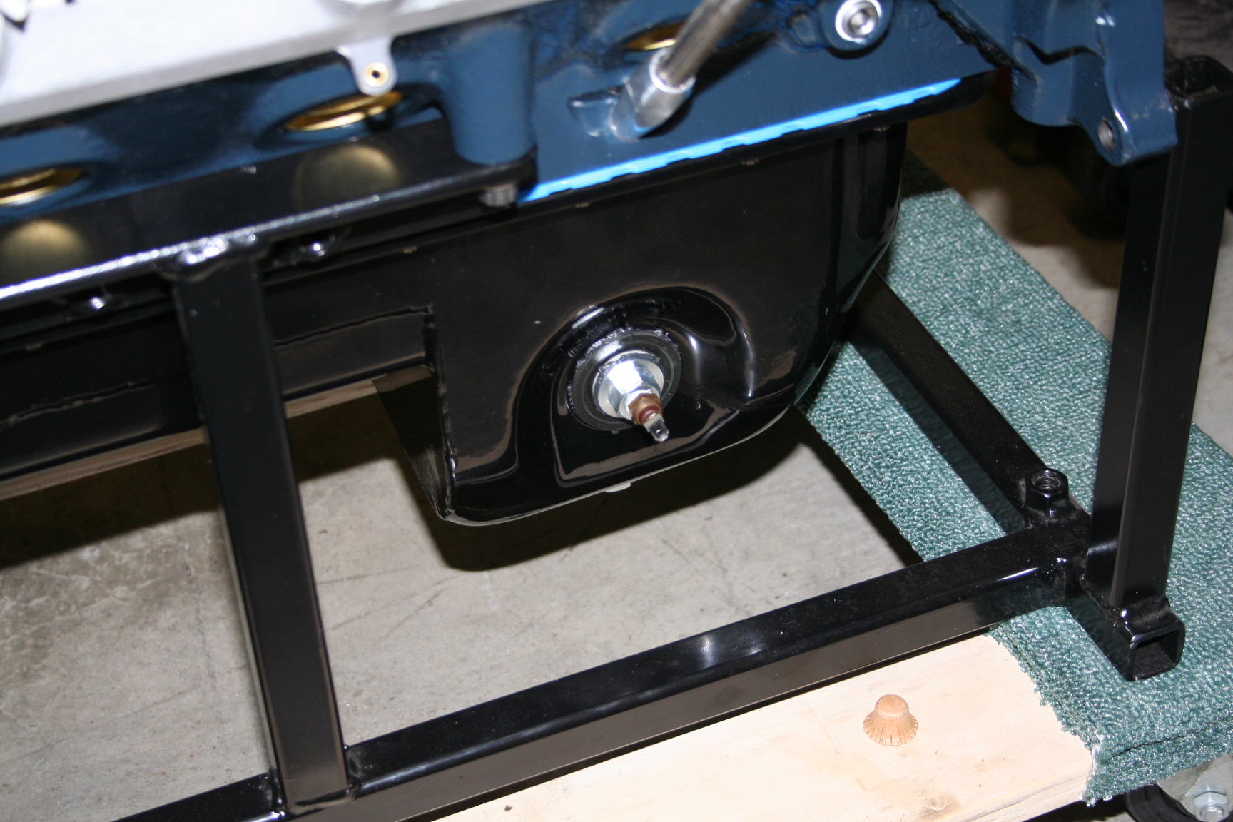
I also drilled and
tapped some threads to accept the Mazda water temp sender into the
20mm x 1.5 plug on the side of the oil pan. This is the spot
where the oil level is normally measured in a Mustang. Since
I'll be reading water temps with a separate gauge, I wanted the
original gauge to do something instead of sit there dead. I
decided to make it read oil temps from the pan. I'm not real
sure how useful this will be, but I'm going ahead with the
plan. I have a spare water temp gauge that was already
modified to work linear with temperature changes, but I might
alter a couple resistors to get a more useful temperature range.
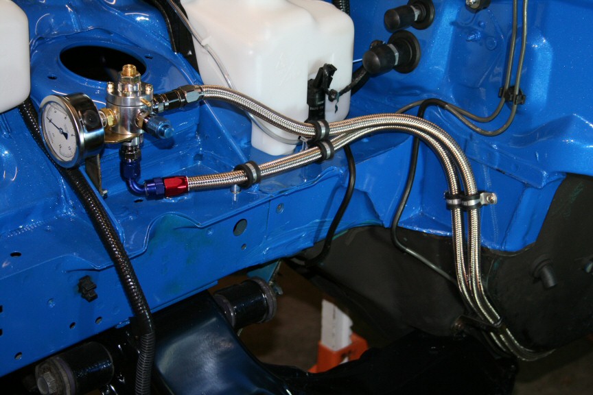
3/22/09 My fuel flow
rate and pressure regulation test went well. I have
confirmed that with using the Mallory 4309 pressure regulator
adjusted to 5-6psi, the stock 5/16" fuel delivery and return
lines along with the stock pump delivers an appropriate amount of
fuel.
I also made a
bracket to mount up and hold my MSD 6AL. It's not wired in
yet; just mounted there for now to check fitment and plan how I
want to wire it up.
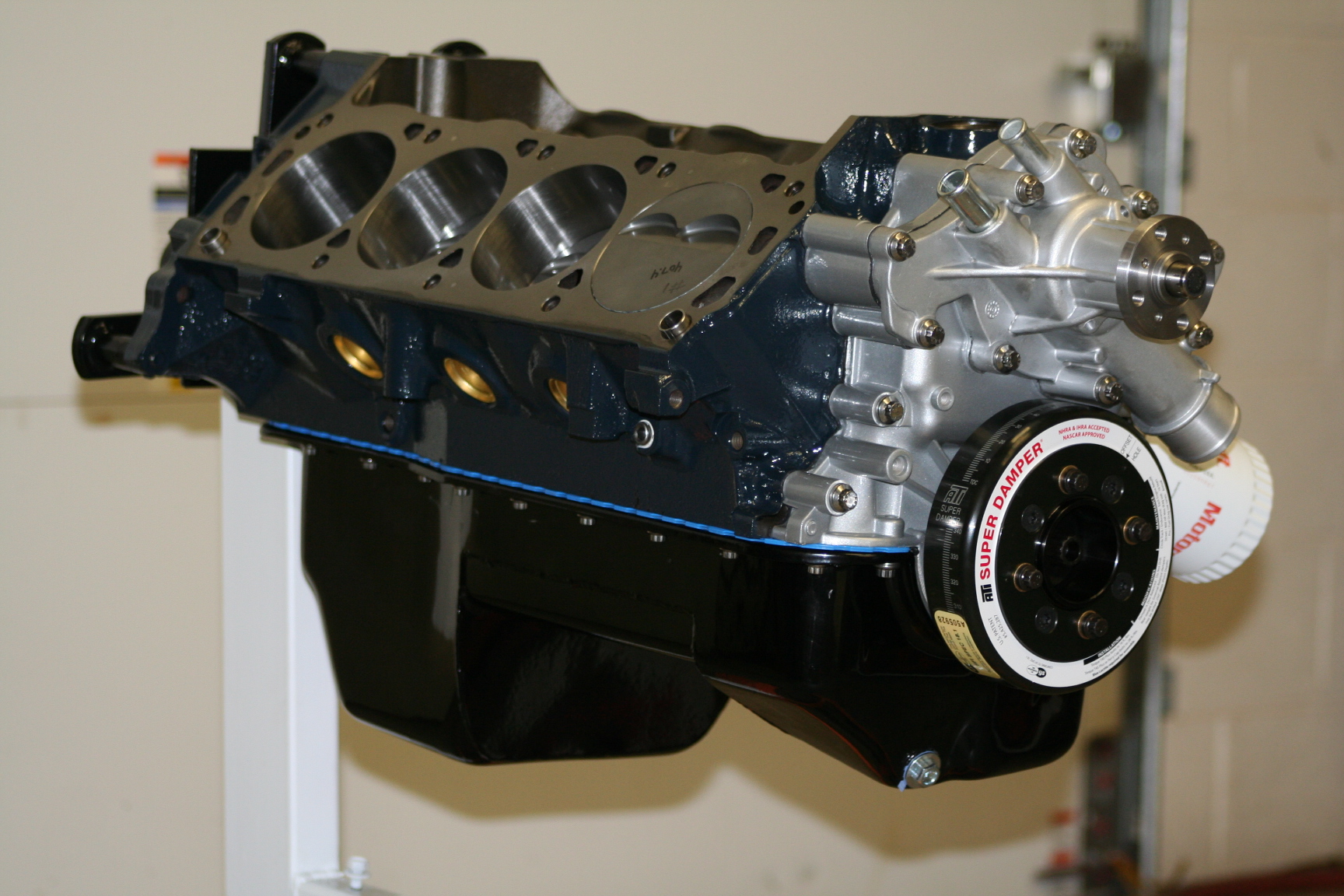
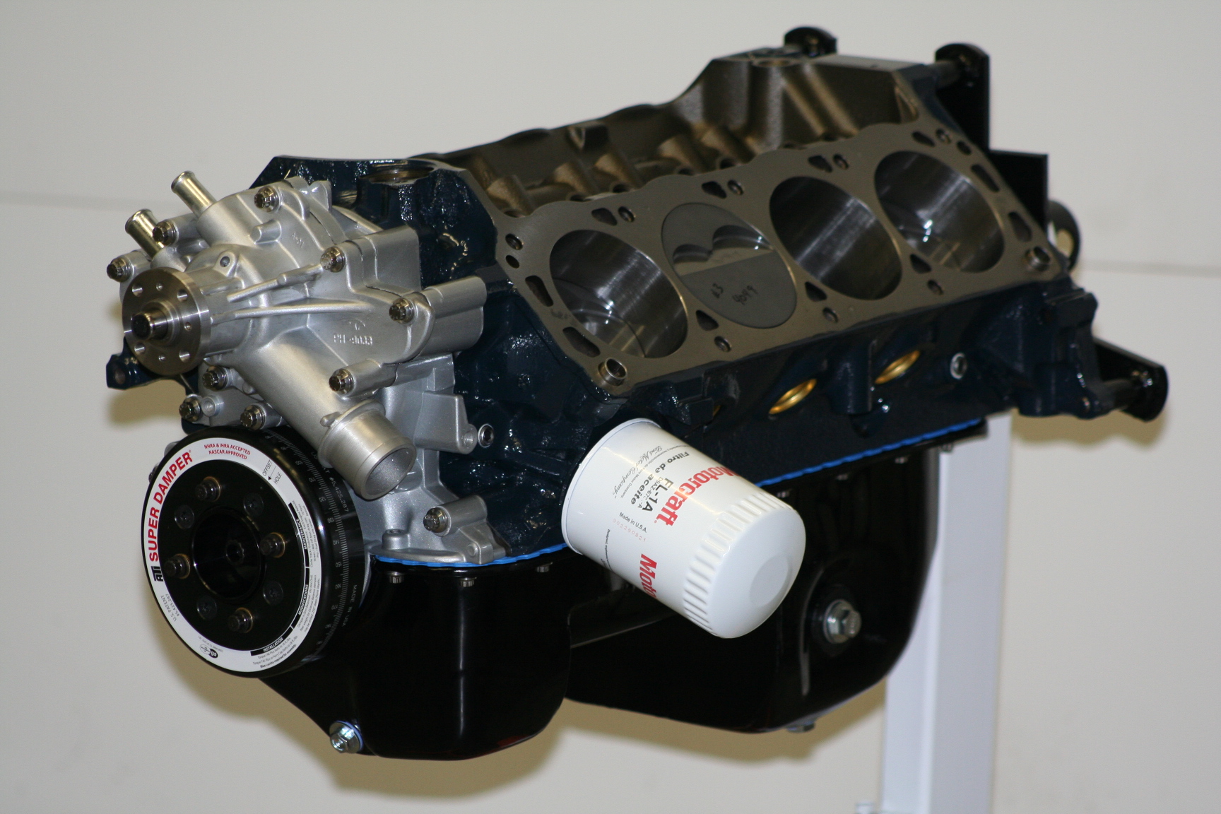
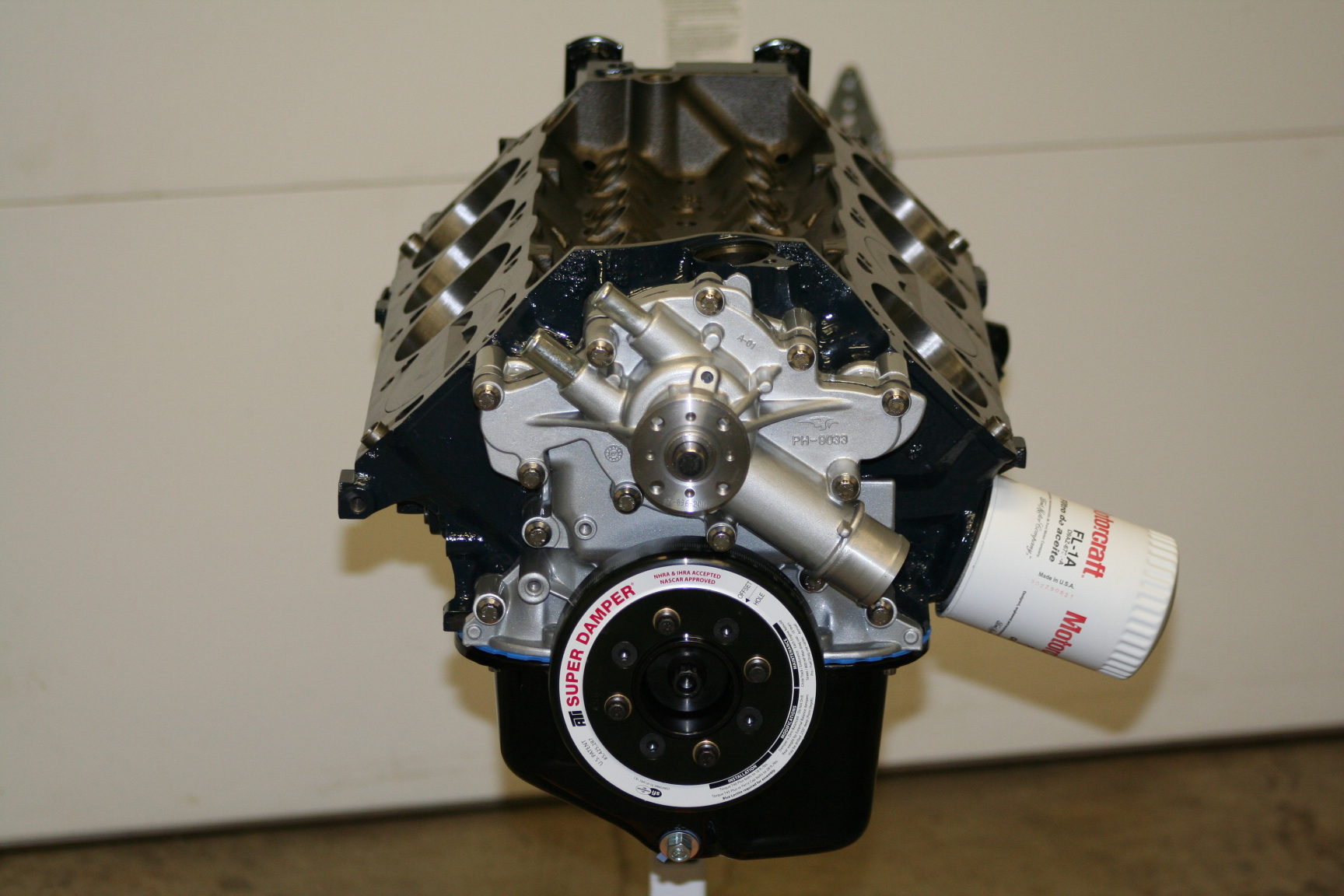
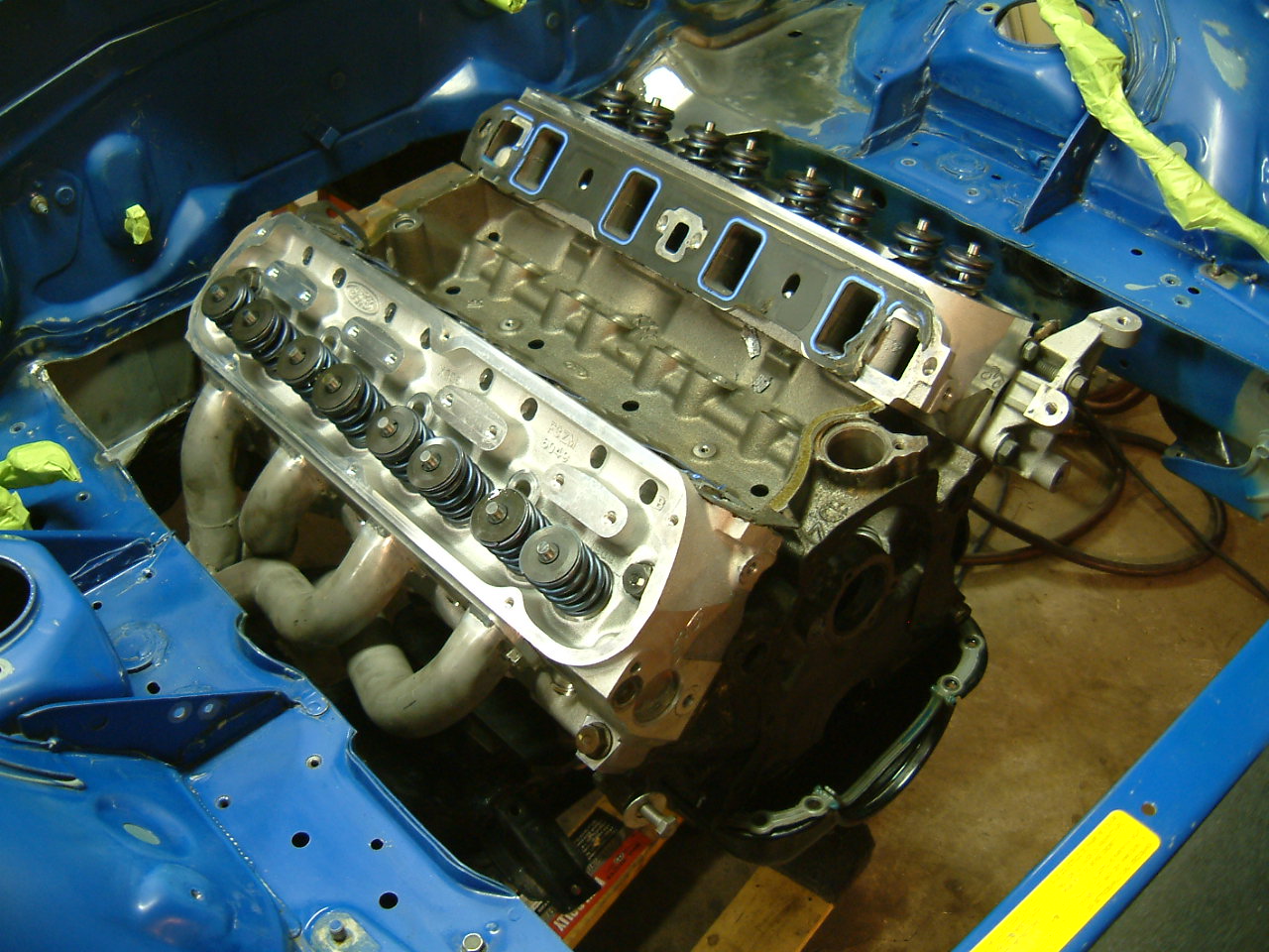
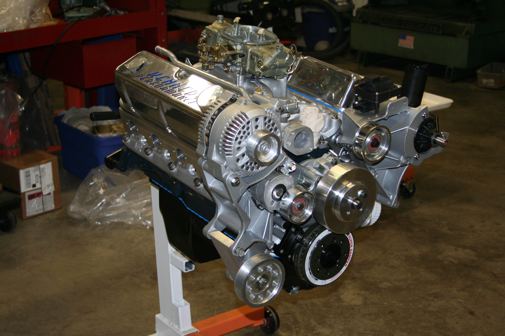
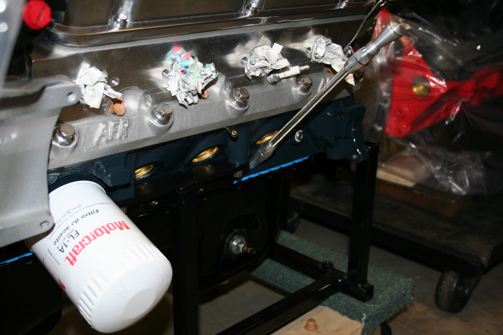
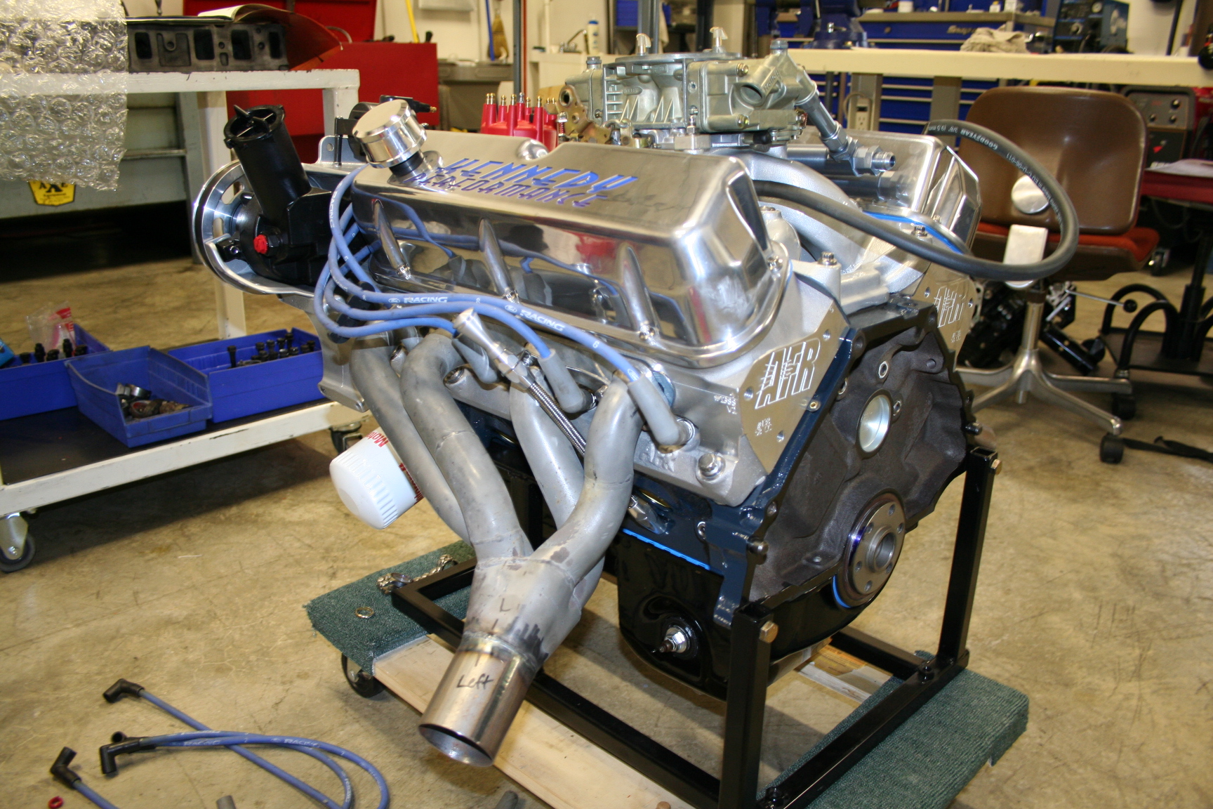
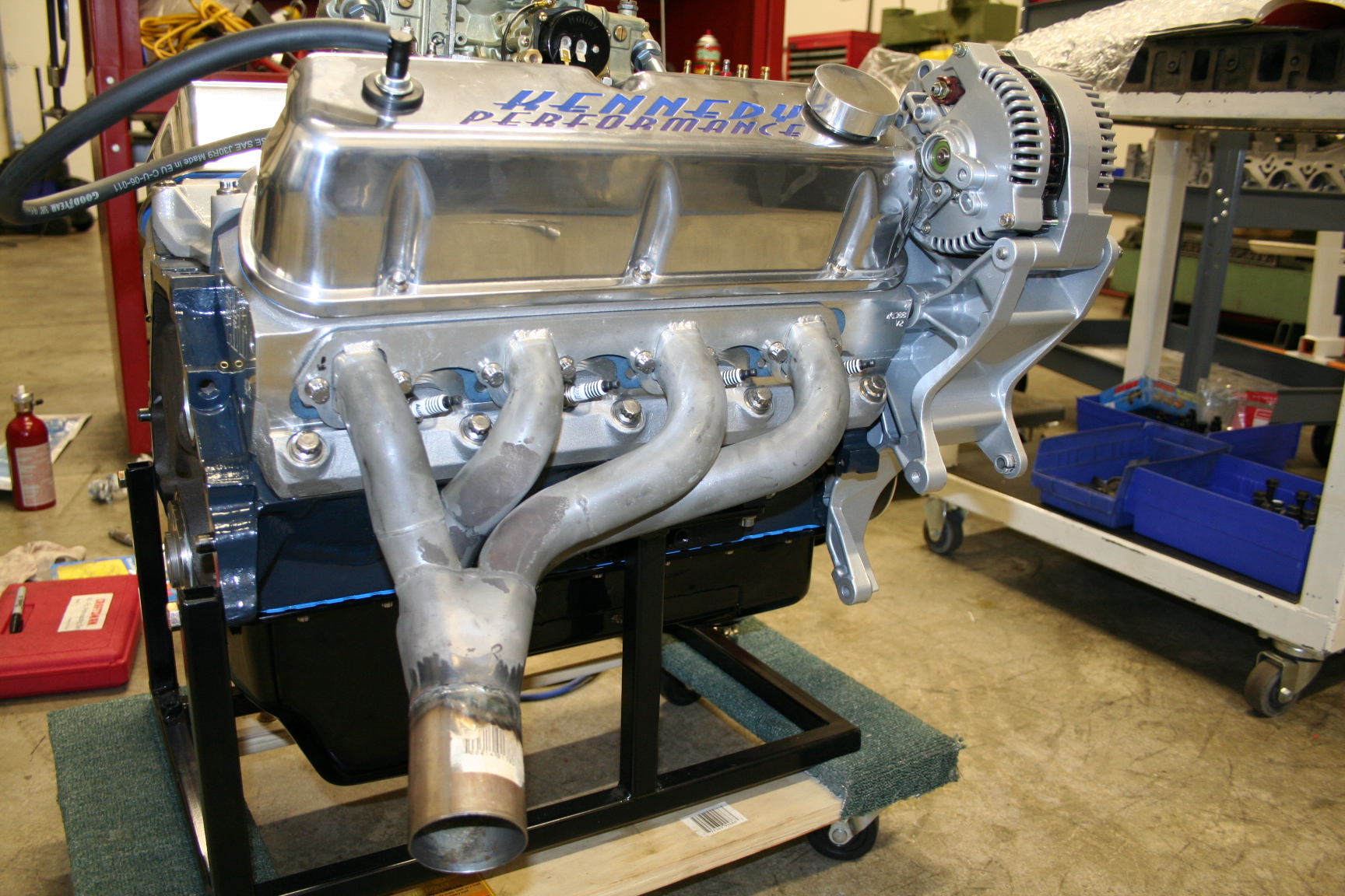
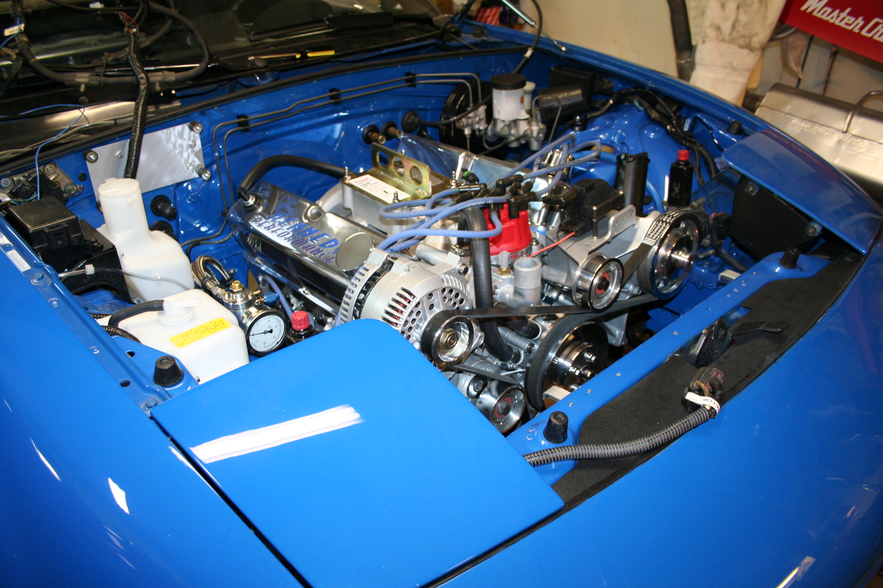
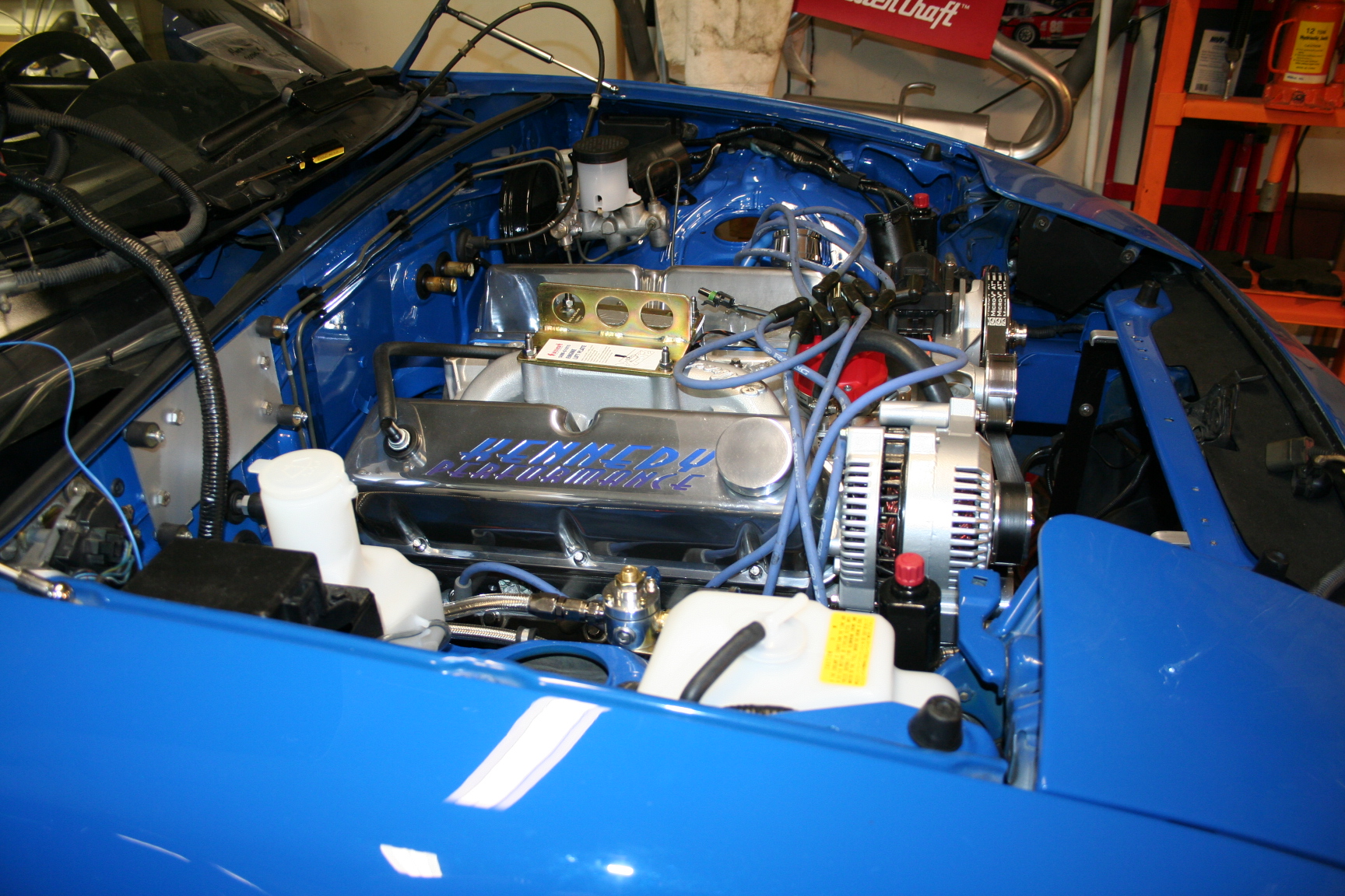
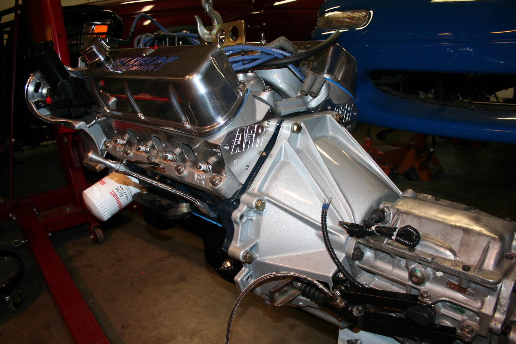
The carb I have is
a Holley 4777 which is their basic 4150 design with a flow rate
spec of 650cfm. I had this carb worked on by Competition
Fuel Systems and it is a bit more adjustable now. I had the
choke removed for performance purposes but cold starts should be a
little challenging. To counter this, I'm going to hold the
throttle open a little to let the engine idle high while it is
warming up. I installed an electric choke actuator and had
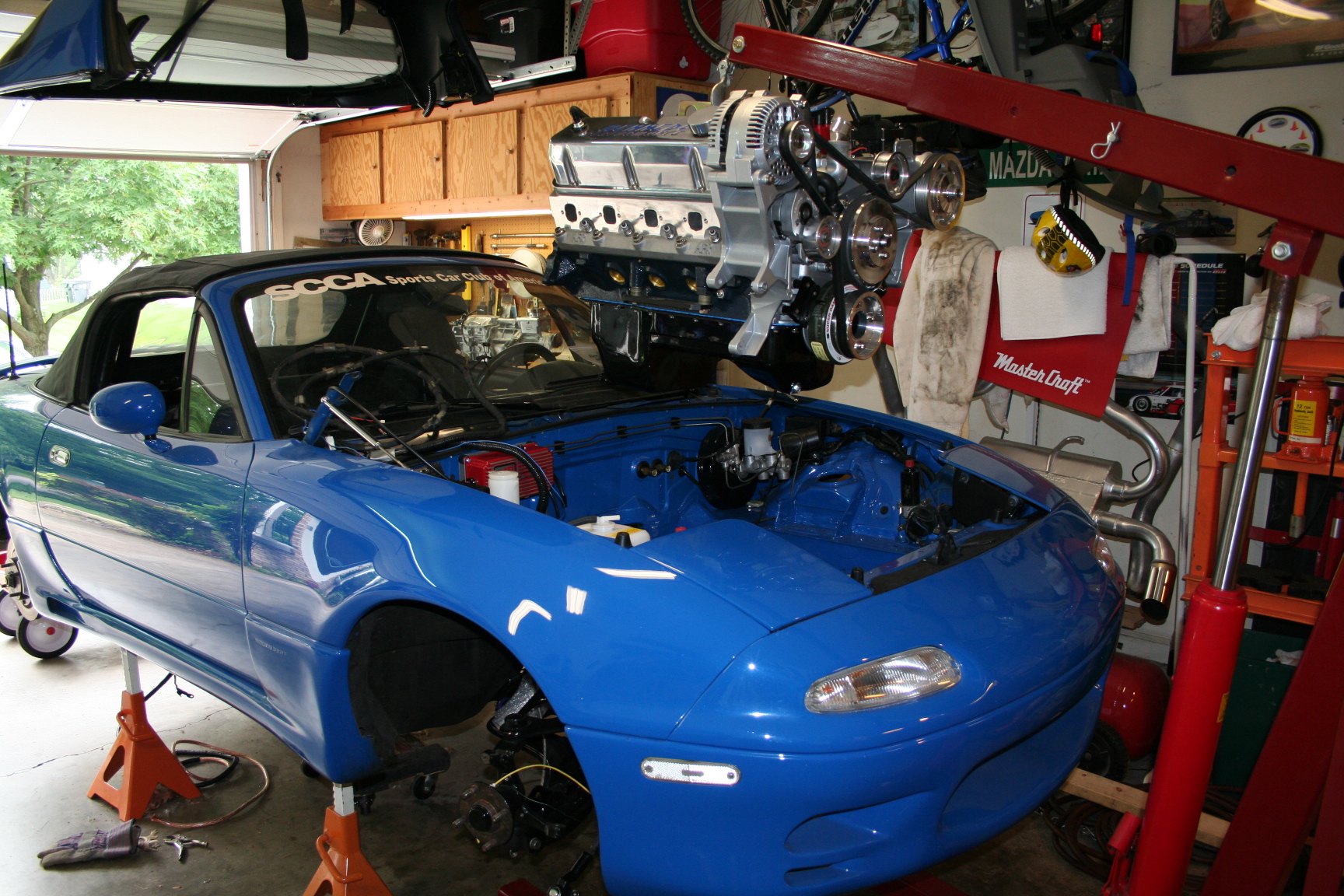
to make a minor mod to it as well. The partial engine in
these pics is a blown block that I borrowed from a friend while I
wait on my own.
I also modified my
headers. Since these headers were used, the 3 bolt flanges
were bent. I cut them off and had 3 inch long, 2.5" dia
straight pipes
added as I'm going to do a lap-joint with a band clamp
instead. The headers will be sent off to Jet Hot for a
coating of Extreme Sterling to combat the heat emissions under the
hood. The spark plugs are in but the wires are just
temporary for now.
Oh,
and part of the plan has changed: the fuel log is back in and the
heater tubes are now out of the plan. There was an
interference so I gave up on the heater tubes.
4/15/09 The engine is
ready to go to the dyno! As soon as I can get it scheduled,
it will be on it's way to be fired up for the first time.
Hopefully there won't be any major issues, but if there are, it
will be better to catch it on the dyno than the street.
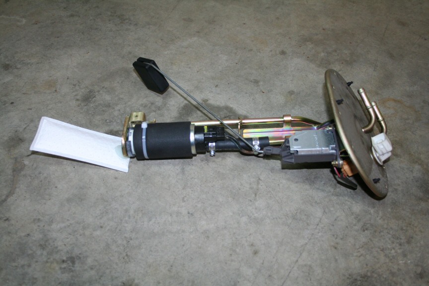
While playing
around with the fuel pump and doing flow/pressure control tests, I
think I damaged my fuel pump. So, a Walbro 190 went
in. It was cheaper than a stock or Autozone pump. I
didn't need anything special for high pressure, and it turns out
that a Walbro 190 can deliver more than adequate flow at low
(5-7psi) pressures needed for a carb application. I did have
to modify the pick up tube to get the pump to connect to the tube,
but it wasn't too hard.
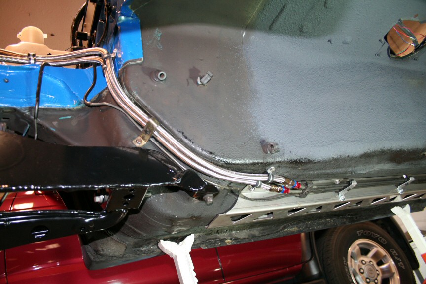
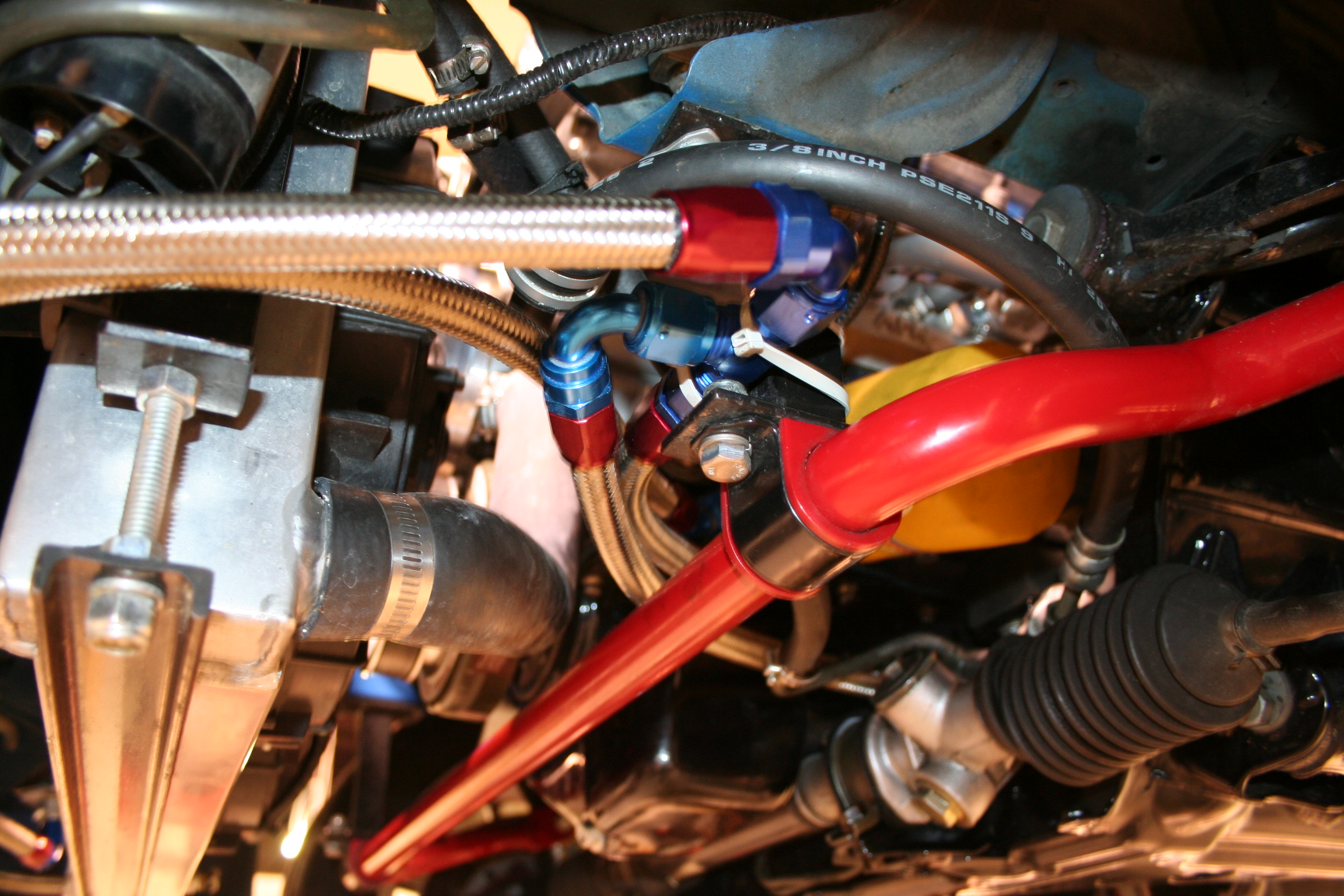
The fuel lines have
now been plumbed to the pressure regulator and tested for
leaks. With some Earls and Russell fittings, I went from the
5/16" fuel line to a -6AN hose. I clamped it down in
certain areas to keep the hoses from rubbing critical parts.
I also have the FM frame rail reinforcements and positioned the
fuel line next to the rails so that when the tranny support
bracket goes on, there is clearance.
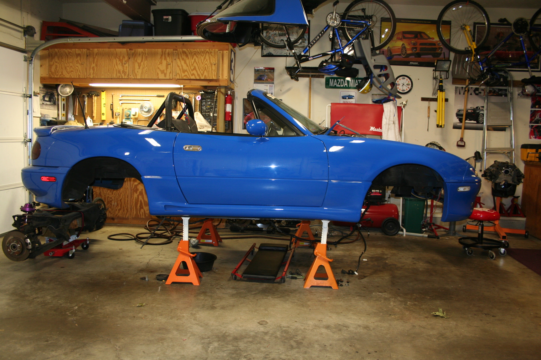
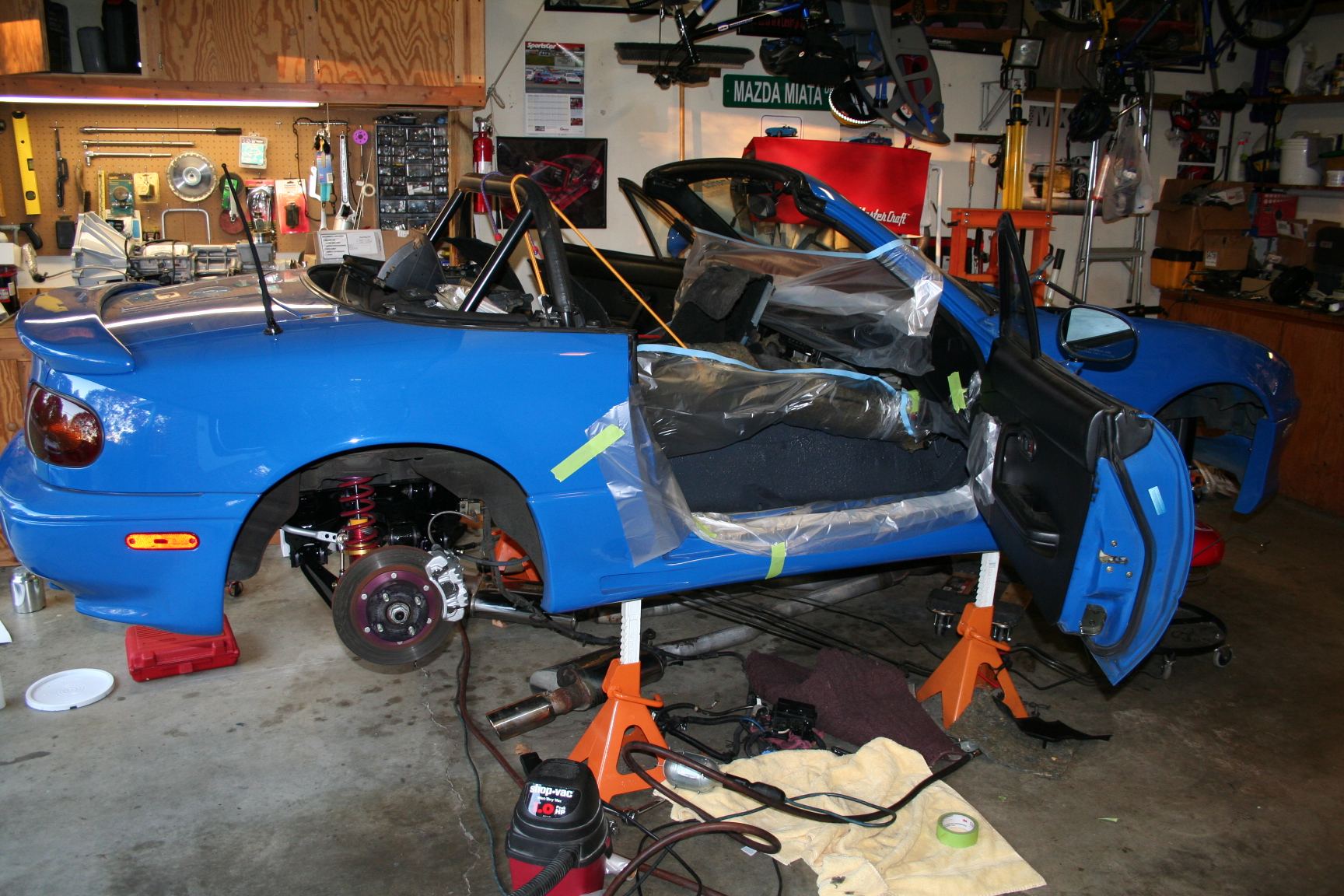
4/28/09 The engine
still hasn't had a chance to make it to the dyno. Long
story, but basically waiting for the dyno to be available.
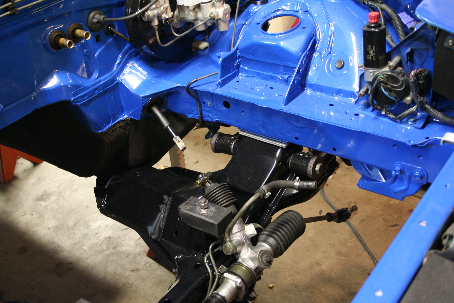
In the mean time, I test fitted the engine in the Miata. It
fits! Well, mostly. I'm having to make a few
adjustments with the power steering rack and hard metal
lines. There will still be a lot of massaging to get it
right, but this is a start.
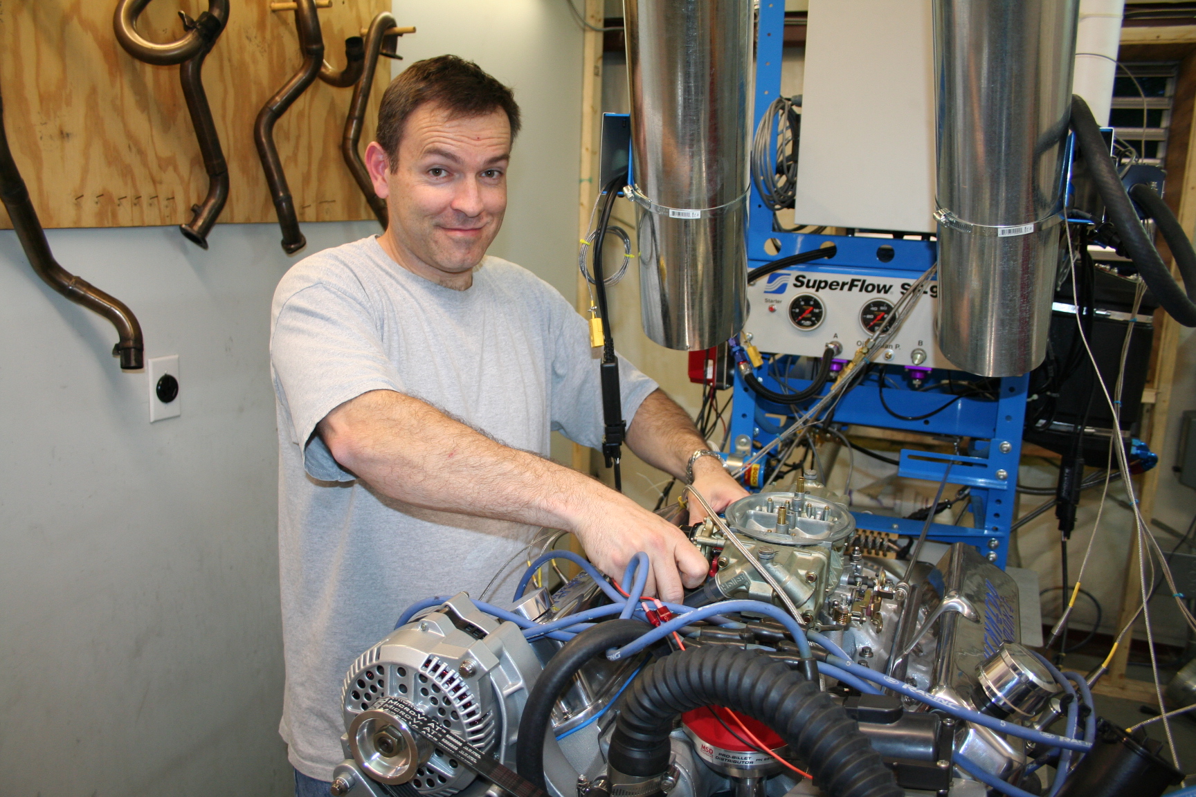
5/18/09 The engine finally got tested on a SuperFlow dyno.
After several fuel jet changes, we ended up with power/torque
peaks of 412hp/399ft-lb SAE. No major problems found on the
dyno. Here's a video of the engine running.
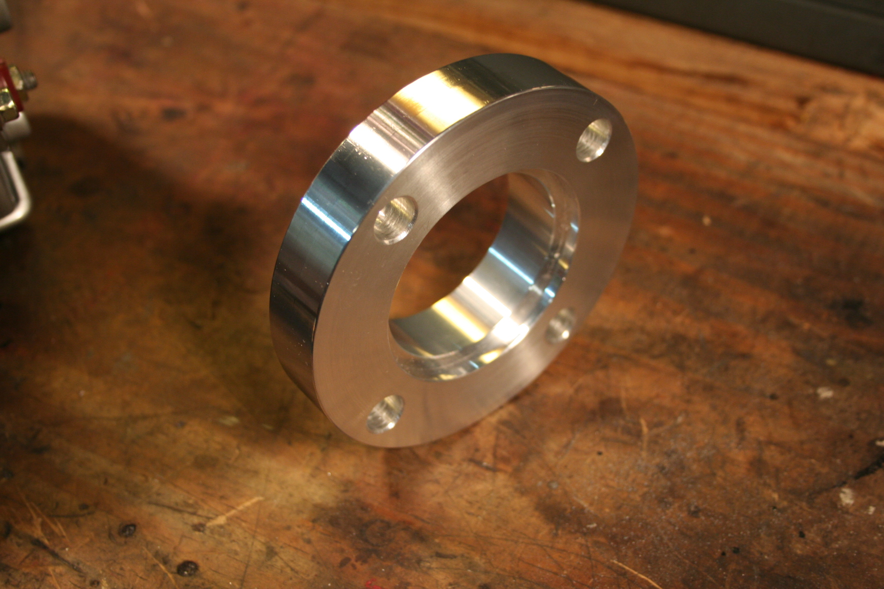
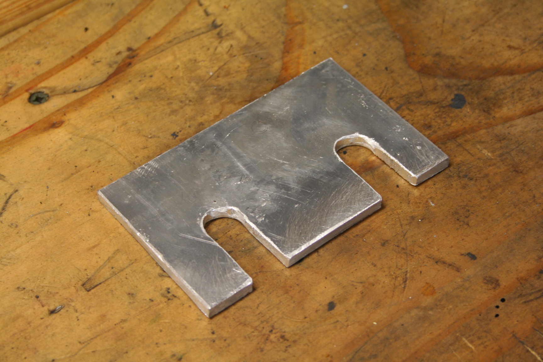
6/01/09 I went ahead and made spacers
to drop the subframe down 1/4 inch in anticipation of hood
clearance issues. With the engine still out, it was a little
easier to design and fit the spacers. I'll also need
1/4" spacers (washers) per bolt to space down the rearward part of the
subframe.
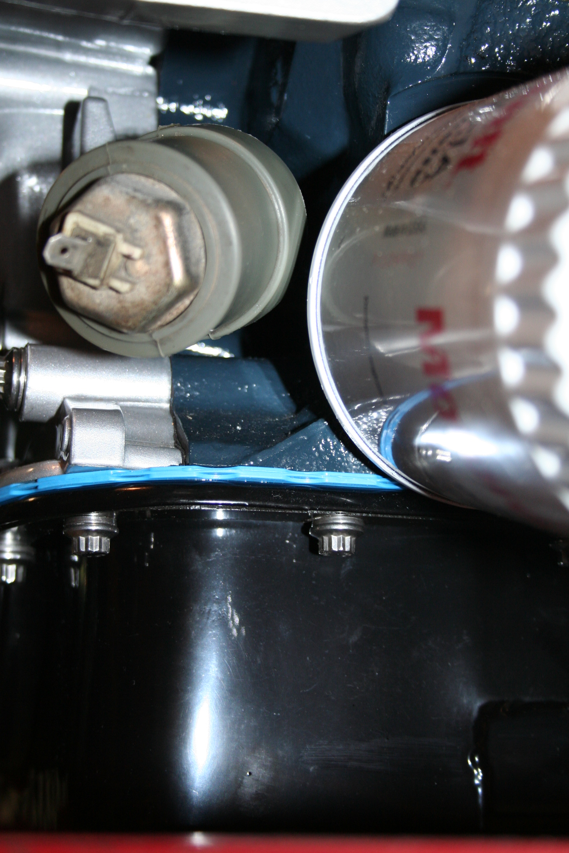
I also mounted the original Miata
oil pressure sender to the block. I chose to use the Miata
sender instead of the Ford one so that the oil pressure gauge
would work as normal. Apparently the Ford sender can be made
to work with a resistor, but I've heard that folks still had
trouble getting the gauge to read right. The Miata sender
attached to the block with two brass fittings: a 1/4" male
NPT to 1/8" female NPT adapter, and a 1/8" male NPT to
1/8" female NPT 45 degree elbow. The Miata sender is a
1/8" male NPT, and the Ford block is a 1/4" female NPT.
It mounted up nicely and doesn't appear to have any interference
issues.
6/10/09 I took a day off work to focus
(mostly) on the Miata. While it wasn't unproductive, the net
result of progress on the car was almost zero. I dropped the
engine in and made some adjustments to the washers used to space
the engine up high enough to clear apparent interferences with the
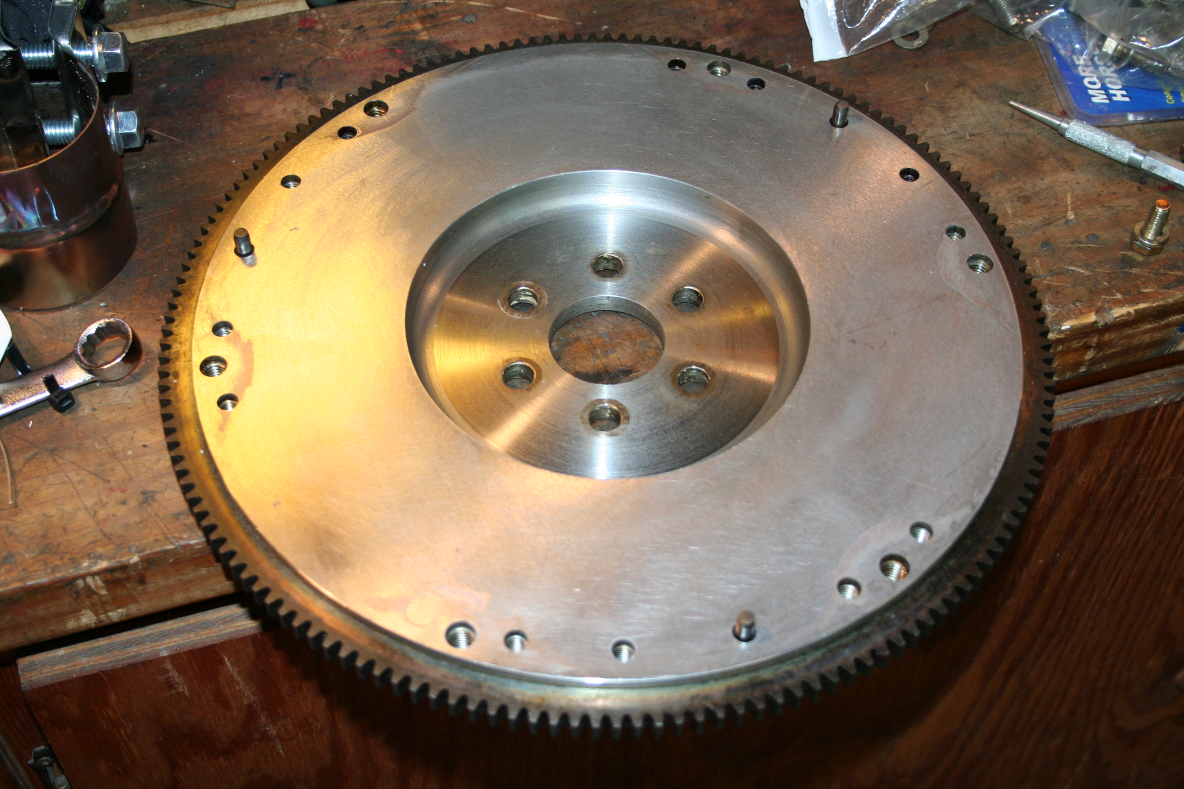
steering rack. Next up was the flywheel and clutch. I
had to locate new flywheel locating dowels as my flywheel was
missing them. After that, the clutch went on just fine. I
tried mounting the bell housing before the tranny. The
tranny wouldn't mount up so I removed the bell housing and
attached it to the tranny. I then tried mounting the bell
housing/tranny to the engine and it still wouldn't seat
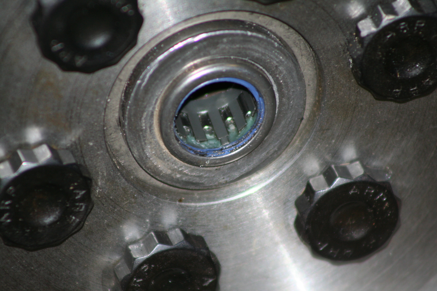
right. It turns out the pilot bearing is damaged and
possibly not seated all the way. I had to remove the engine
to figure this out. So much for progress.
6/12/09 I got the pilot bearing
out. What a pain that was! The puller I borrowed from
Advance didn't help. The insides of the bearing just broke
apart and I had to use my Dremmel with a tungsten metal cutting
bit to eat up the old bearing housing. The bearing came
right out after the cutting was complete. I bought a new
bearing and put it in the freezer for a couple hours. It
helped a little with getting it to drift into place. I
mounted up the tranny just to make sure it will all fit together
this time. Ahh... yes, it looks like things are better this
time. Now, time to find time to work on the car again.
6/17/09 Engine is in. Tranny is
in. Drive shaft is in. Starter is in. It looks
like the driver side valve cover is going to be a problem with the
heater core pipes. I may have to go with different valve
covers. I'm also working on bolting up the headers.
What a pain so far.
6/20/09 I test fitted an air cleaner
assembly. This is a 7/8" drop base, 14" x 3"
tall filter. and chrome lid. I didn't put the hood on, but I
know it would slightly interfere just by looking at it. I'm
going to try a 2.5" tall filter and test fit the hood.
I don't want to go any smaller as I'm afraid the filter may cause
some restriction issues. There are filter elements lids that
go on top of the filter that I might try, but I really like the
look of the chrome ones better. And hey, after all it has to
look right, eh?
Headers are now bolted in
place. The steering column is now bolted to the rack (man,
that was a major pain to get the splines to cooperate). I'm
also working on the wiring connections to the starter and routing
of the new battery cable under the car.
6/26/09 I swapped out the filter
element for a 2.5" tall K&N filter (p/n E-3735).
Hopefully I'll get a hand tomorrow and mount the hood to check for
clearance. I think it will clear, but very close. I
tried a couple other shorter valve covers; one had problems with
the baffle hitting a rocker arm, the other had an interference w/
the alternator. For now, I'm still trying to make the tall
valve covers work. I also spent a little time today working
with the drive train angle. I don't have a lot of faith in
the angle finder I have, but I think I have the angles
close. Engine and diff axes are parallel within 1 degree,
and about a 2 degree operating angle on each end of the drive
shaft.
6/30/09 My dad helped me mount the
hood and to my surprise, there was about 1 inch of hood
clearance! Since I had the radiator out, I was able to climb
into part of the engine bay with the hood shut and could actually
see the clearance. The top of the filter (wing nut area) had
plenty clearance too. I swapped out the 2.5" K&N
for a 3.0" tall K&N (p/n E-3737) and everything still
fits fine with about 3/8" hood clearance.
I also finished up some smaller yet
time consuming things with the fuel line going to the carb, wiring
to the dizzy and coil, and worked a bit on the wiring going to the
starter. The challenge here has been heat issues w/ wires
near the headers.
8/12/09 The last month has been
busy, both on the car and non-car related. Progress is being
made on the brakes, exhaust, power steering and cooling
system.
Brakes is the Monster Miata system
with big Wilwood Dynalite 4 piston calipers in the front, 2nd gen
RX7 calipers in the rear, and 11" vented Wilwood rotors on
all four corners. I have also needed to massage the hard
brake lines around the headers to reduce heat transfer to brake
fluid.
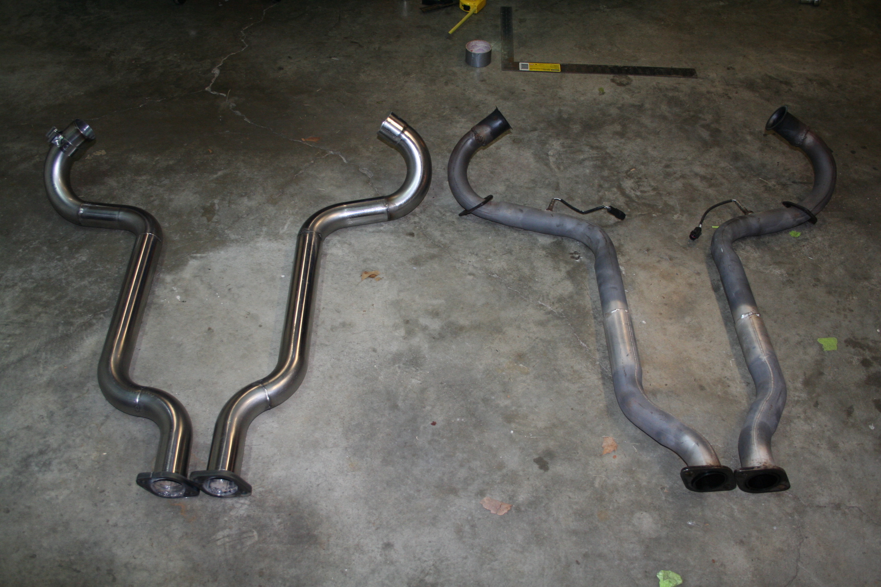
I'm using an existing
V8 miata exhaust system from a friend/prior V8 miata owner, except
for the section that goes from the headers to the X-pipe.
Down the road, I might recreate the X-pipe-back section. I
made these pipes out of 2.5" stainless steel. It was a
bit of work, but quite enjoyable and perhaps a performance
improvement. The old exhaust was crimp bent and 2.25"
at best.
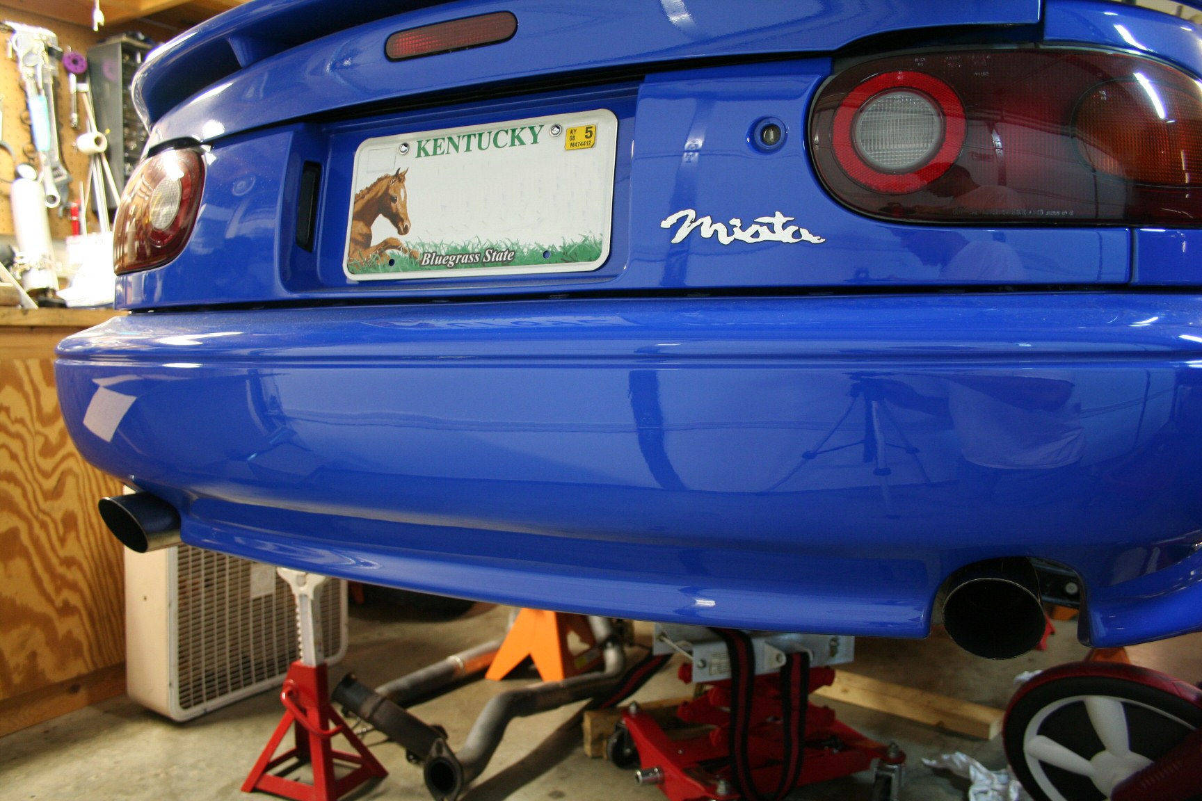
I swapped out the tips on the
existing exhaust for some that were similar to what I had with the
turbo. These are pretty simple looking, but I like
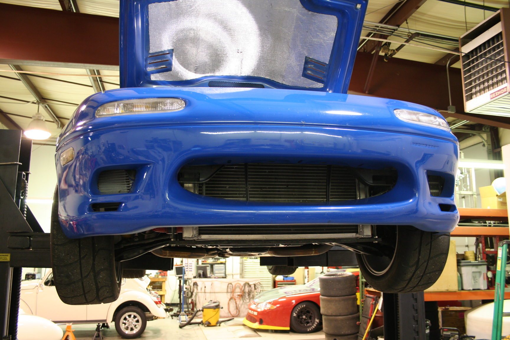
them. They are 3 inch slant cut. Since I have a
fiberglass Racing Beat bumper, I didn't want to just cut the left
side for the 2nd exhaust tip. Instead, I removed the bumper
and had Steve Kelley with SRC Collision modify my bumper to
replicate the tunneled cutout for the 2nd tip. It turned out
great! Thanks Steve!!!
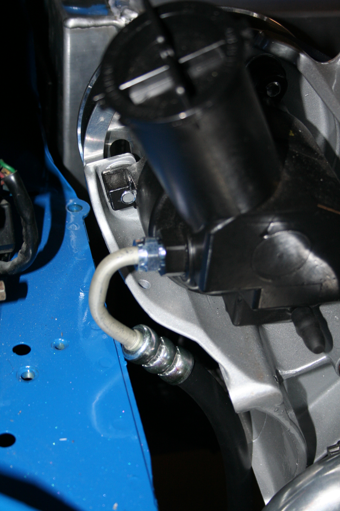
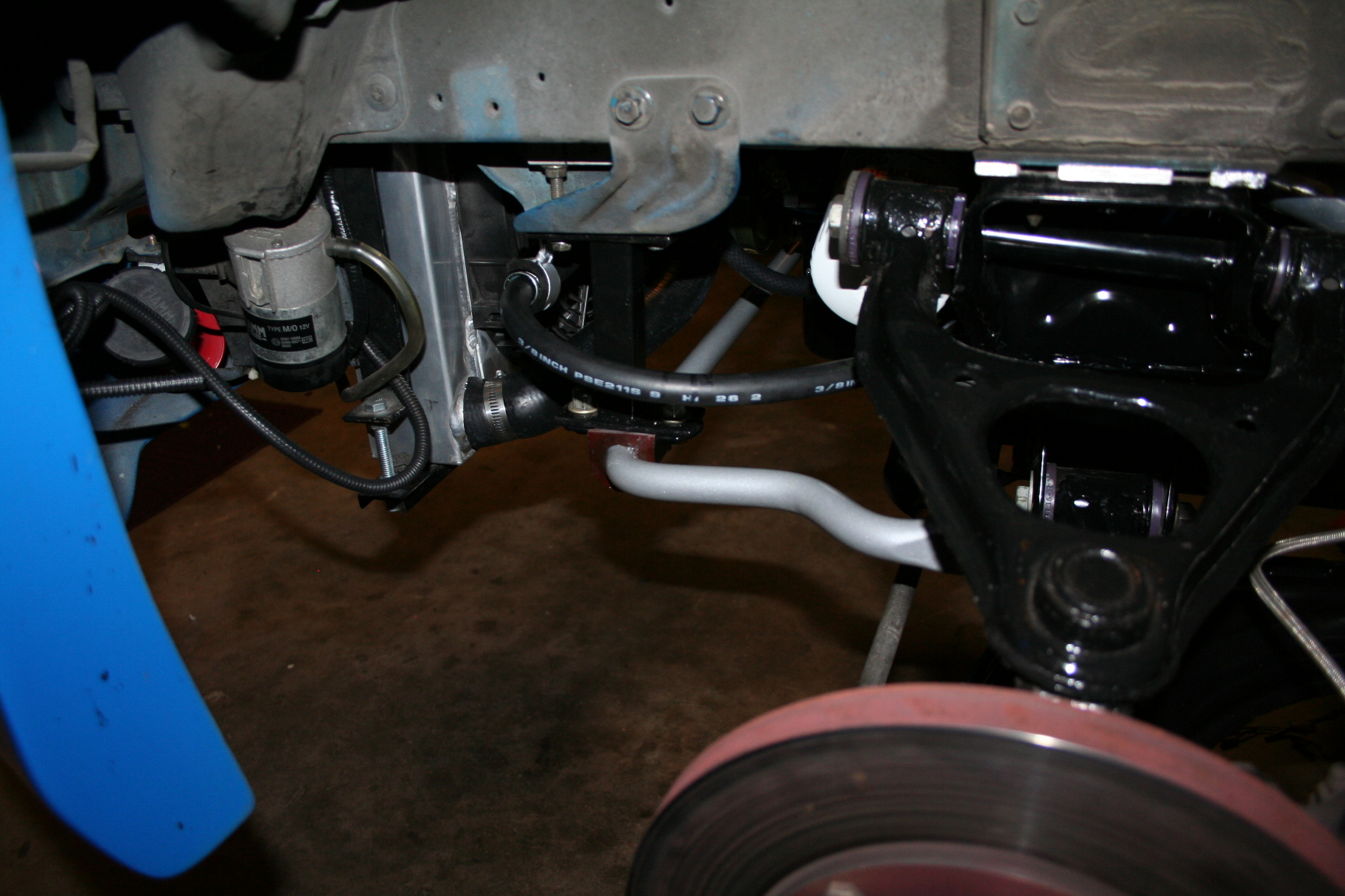
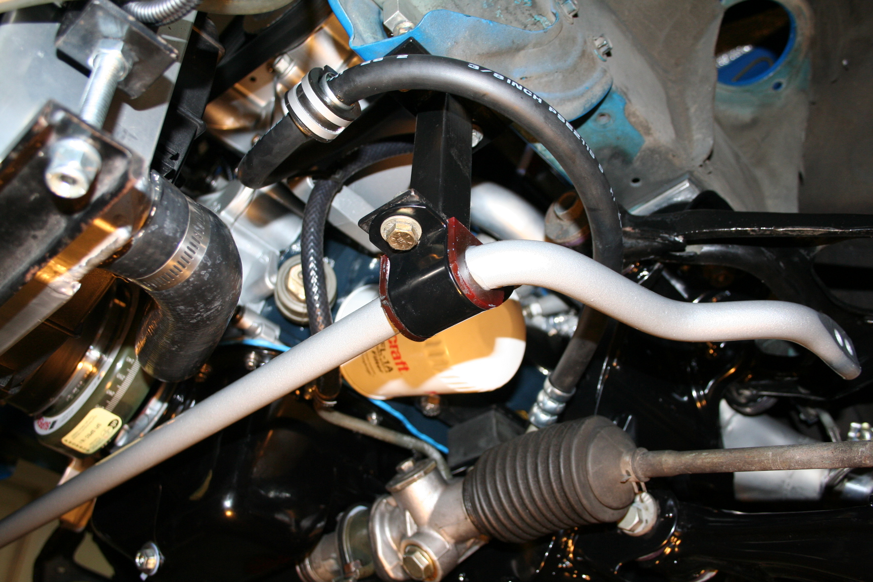
One challenge I'm
working through is figuring out a good way to plumb the Ford PS
pump to the Miata steering rack. I've tried starting with a
couple Ford PS pump lines and am getting close with a little
bending, but I'm not quite there yet. Currently, I have a
swivel end '93 Mustang hose attached to the pump and have bent it
a bit to stay away from the sharp edges. I had fitting on
the rack end of the Ford hose cut off and had the original Miata
fitting put on. The metal tubing of the end of the hose that
connects to the rack on the Ford line was the same diameter as the
original miata line, so slipping on the Miata fitting to the Ford
line and flaring it was pretty straight forward. I also
modified an existing Miata bracket to support the PS hose and
reduce strain on the rack fitting. I ended up mounting the
bracket to the sway bar mount and clamped over the hose on an
existing metal mount that was on the Ford hose.
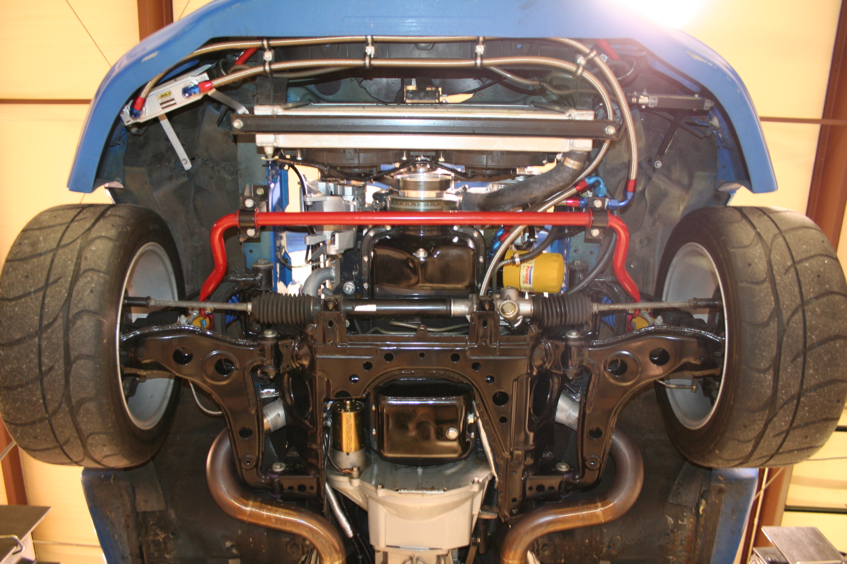
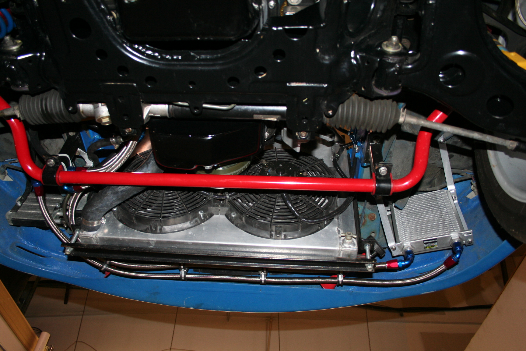
As for the cooling system, I ran
into a problem with plumbing the radiator inlet to the
engine. Also, I still needed to mount the fans and
needed a good baffling plan to channel air to the diff. I
hired Adam McFadden to modify my radiator with a fan shroud
and mount fans (3/8" from core). He also modified
my coolant inlet port some. I modified it a little more by
melting and re-soldering the filler cap portion to rotate the
over-flow port in a better direction. I'm happy with the
result. It's a simple, down hill path going from the filler
neck to the radiator upper port. The fan shroud turned out
good as well. Supposedly this shroud will help with cooling;
it has to help when the fans are running, but I'm concerned that
the fans are pretty much going to be running a LOT as the shroud
would likely block a lot of air flow from just air being pushed in
while the car is moving. We'll see. I still need to do
a little more shrouding of the radiator to the nose.
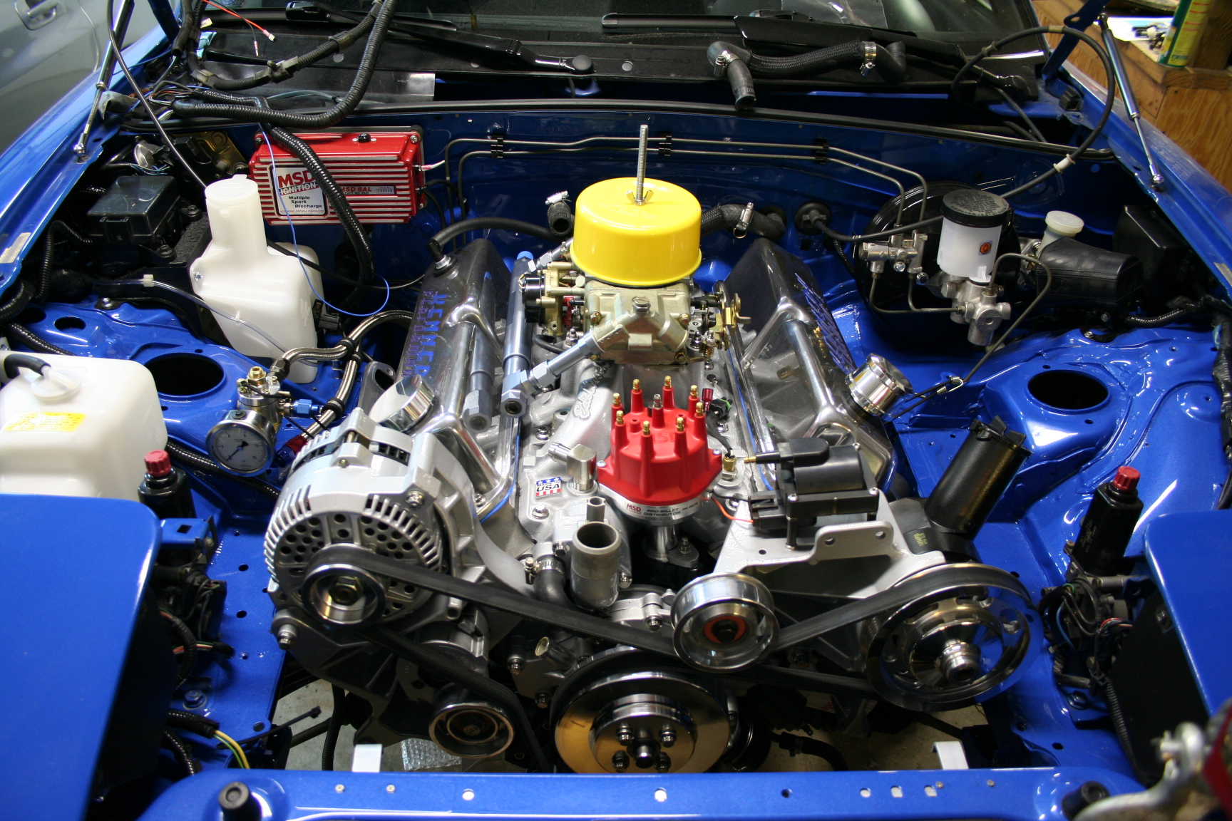
8/17/09 It runs! Well,
I spent the last few evenings and a good part of a weekend
focusing on firing up the engine. I hooked up the water temp
and WBO2 sensor gauges, put in the seats, finished the interior,
bled the brakes, retightened a few bolts, fill the tank with gas
and turned the key. IT RUNS! Well, not without a few
bugs but I'll get on it soon. The suspension alignment is
all out and the ride height is sitting way too low. I took
it for a test drive and scrapped the exhaust just pulling
out of the driveway. Will be fixing that soon, along with a
few other bugs. I had a few friends over to watch it happen
(either start or blow up). Thanks to my friend Bijan for the
video! The pic above is from my friend David Brown who took
a shot about 15 minutes before turning the key. Notice the
cog webs on the jack stand? It was time to come down!
8/30/09 Ok, now that I've had a few
days to calm down from all the excitement of starting it up, I've
started working on sorting out some of the bugs. As for
ground clearance issues, I made big strides by addressing 4
different areas. First, I removed the 1/4 inch shims that I
originally had put in between the K-frame and chassis. It
turns out that without the shims, I still have about 3/8 inch
clearance in the tightest spot between the air cleaner and
hood. Second, I adjusted the exhaust and now have it tucked
up closer to the body. Third, I adjusted the Ground Control
spring perches up to raise the entire car. Forth, I had
forgotten to check the tire pressures before I took the car for a
test drive and they were very low. All of these changes
increased my ground clearance from about 1 inch to about 4 inches.
While I had the car up on jack
stands again, I noticed a couple leaks. The first one was
engine oil. It appears that I already scrapped my oil drain
plug - not a good thing. I checked it and it was a bit
loose. The leak looked to be coming from the drain plug so
hopefully that was it. The second leak is transmission fluid
and it appeared to be coming out of the speed sensor/speedometer
cable adapter. I pulled the sensor and not only does it have
a crack in it, it appears it may be missing an o-ring. I'm
going to replace the sensor with a new one. Also, the
speedometer wasn't working so hopefully reassembly with solve the
problem.
I did get a chance to drive the car
again after eye-balling the alignment a bit, and wow is it a
handful to drive! Easy on the throttle in 1st gear or the
tires start screaming at you.
Another problem that I'm still
thinking through has to do with the difficulty I'm having starting
the car after it has had a chance to warm up and sit for an hour
or so. I'm hoping that I'm just flooding the engine, but I
fear it's vapor lock. Looking at how I have the fuel line
going from the regulator over to the fuel log, that's a long
section of fuel that gets well heated from the engine and doesn't
have the benefit of being re-circulated into the fuel tank.
I'm fearing that this relatively slow moving fuel gets overly
heated and since it goes no where but to the carb, it is causing
fuel boiling problems. I'm going to try a different shut down
procedure by shutting the fuel pump off several seconds before
shutting the car off. Hopefully this will help drain the
bowls before the engine shuts off and will help hot restart.
10/10/09 Since the last update, I've spent a bit of time adjusting
the carburetor. Between swapping out main jets, transition
air bleeds and adjustments to idle mixtures, as well as some base
and advance ignition adjustments, I've been able to improve my
fuel economy a bit. When I first started, I was pig rich in
pretty much all conditions and got a whopping 8mpg. I
measured the mileage at the last fill up and I'm up to about 12mpg
now. That was mostly in city driving. If I can get to
14-15mpg without giving up too much power, I'll be pleased.
I have a new vacuum distributor on my work bench to replace my
mechanical-only distributor, but I was told that since my cam has
a lot of duration, there will be significant limitations as to how
much vacuum advance I can utilize w/o running into drivability
problems. I'll give it a shot soon.
I now have a 3/8" phenolic
spacer between the carb and manifold. This has helped
slightly with the hot restart issue. I'm still working on a
better solution.
I installed an Innovate MAP sensor
and SSI-4 to be able to datalog RPM, A/F and vacuum with my
laptop. Everything works except for some strange RPM
readings. A dedicated ground for RPM might fix that.
I swapped out the coilovers for Fat
Cat Motorsport's package. They include revalved Bilstein's,
adjustable lower purches, 450lb/in front springs, 300lb/in rear
springs and better bumpstops. Compared to my Koni setup,
these do work better. It's not a lot better as the prior
stuff was good, but ride quality over big bumps is certainly
better. The suspension seems to be more compliant with
washboard surfaces as well. I have a touch of oversteer and
a bit more sway so I might be looking at putting in a stiffer
front sway bar.
My first autocross with the V8 was
on 10/4/09. It was the first autocross I've driven in over 4
years and I had an absolute blast. The car drives very
well. The handling is just fine; any notion of a big stupid
heavy V8 engine throwing off the balance is totally false.
I've heard people say that they would think this would be the
case, but I can truly say that it's not the case. Once
again, thanks to Bijan for the great video work.
Block -Machining work by Kennedy
Performance -Seasoned Ford 302 small block
-331 Stroker; 10.2:1 compression
-Bored 0.0030 inches over
-Square Decked & Align Honed
-Eagle forged I-beam rods
-Mahle forged pistons
-Eagle 4340 forged crank, internal balanced
-157tooth/0 balance flywheel
-ATI Super Damper harmonic balancer
Heads -AFR 185
-High spring rate valve springs (to prevent floating/bouncing)
-Titanium retainers (to reduce valve train mass)
-7/16" studs
-Cometic Multi Layer Steel head gaskets
Rocker Arms
-Scorpion 1.6 roller rockers, stud mount
Intake Manifold -Edelbrock Performer RPM Air-Gap
Air Filter Assembly
-K&N 7/8" drop base,
(60-1430)
-2" high, 14" dia K&N filter
Cam
-Flow Tech Induction custom grind
Carburetor
-Holley 4150 (#4777)
-- 650cfm
-- Modified by Competition Fuel Systems
--- Mechanical secondaries
--- No choke
--- Solenoid controlled fast idle circuit
--- 4 corner adjustable air bleeds
-- Mallory 4309 fuel pressure regulator
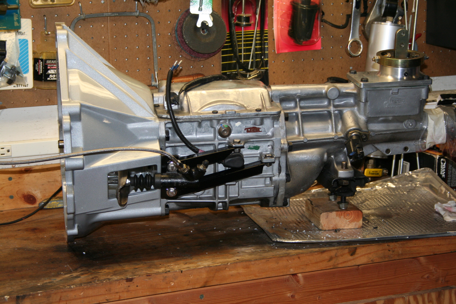
Transmission
-Tremec T5Z/World Class
-(2.95,1.94,1.34,1.00,0.63) gears
-T5/302 bell housing
-Pro 5.0 shifter
-Block alignment plate
*this tranny has a 330ft-lb torque rating and is a direct replacement
of the T5. I'm a little concerned about the torque rating.
OR
-Tremec TKO 600 (p/n
TCET4617)
-(2.87,1.89,1.28,1.00,0.82) gears
* this tranny has a 600ft-lb torque rating and a very nice gear
ratio arrangement for street and track use for a light weight car such
as a miata coupled with a powerful engine that might be herky-jerky
under 2000rpm or so (i.e. cruising a bit above 2000rpm would result
with this tranny). May require longer drive shaft (probably
not)? May require different bell housing. Price is about $600
more than a T5Z.
Ignition -MSD #8579 distributor
-MSD 6AL
-Autolite Racing spark plugs (AR 3932)
Exhaust
-1 5/8" Shorty headers from conversion kit
-2.5" pipe to X pipe
-2.5" X pipe
-2.5" pipe to mufflers
-Magnaflow 2.5"
-3" tips
-Felpro header gaskets (1486)
Engine Accessories
For a 94-95 Mustang GT:
-Timing cover
-Water pump & pulley
-Alternator & pulley
-PS pump & pulley (Wazee)
-AC compressor (note, if no AC is used, just go w/o the compressor or
delete pulley and use a xx" Gates belt)
-Idler and tensioner pulleys (Wazee)
-Alt, crank, water pump pulleys (BlueOvalIndustries)
-PS/AC/ALT compressor brackets
NOTE:
-Close to block design (allows puller fans)
--All parts from:
---'91-'93 Thunderbird (w/ V8)
---'94-'95 Mustang GT
---'96?-'01? Explorer
-Away from block design (pusher fans only)
--All parts from:
---'86-'93 Mustang GT
Misc parts
-Modified dual sump oil pan
-Stock oil pick up
-Melling Select oil pump
-Lokar dip stick/tube
-Lokar throttle cable
-Heater hose Kelly Springfield #4545
-A ton of stuff..
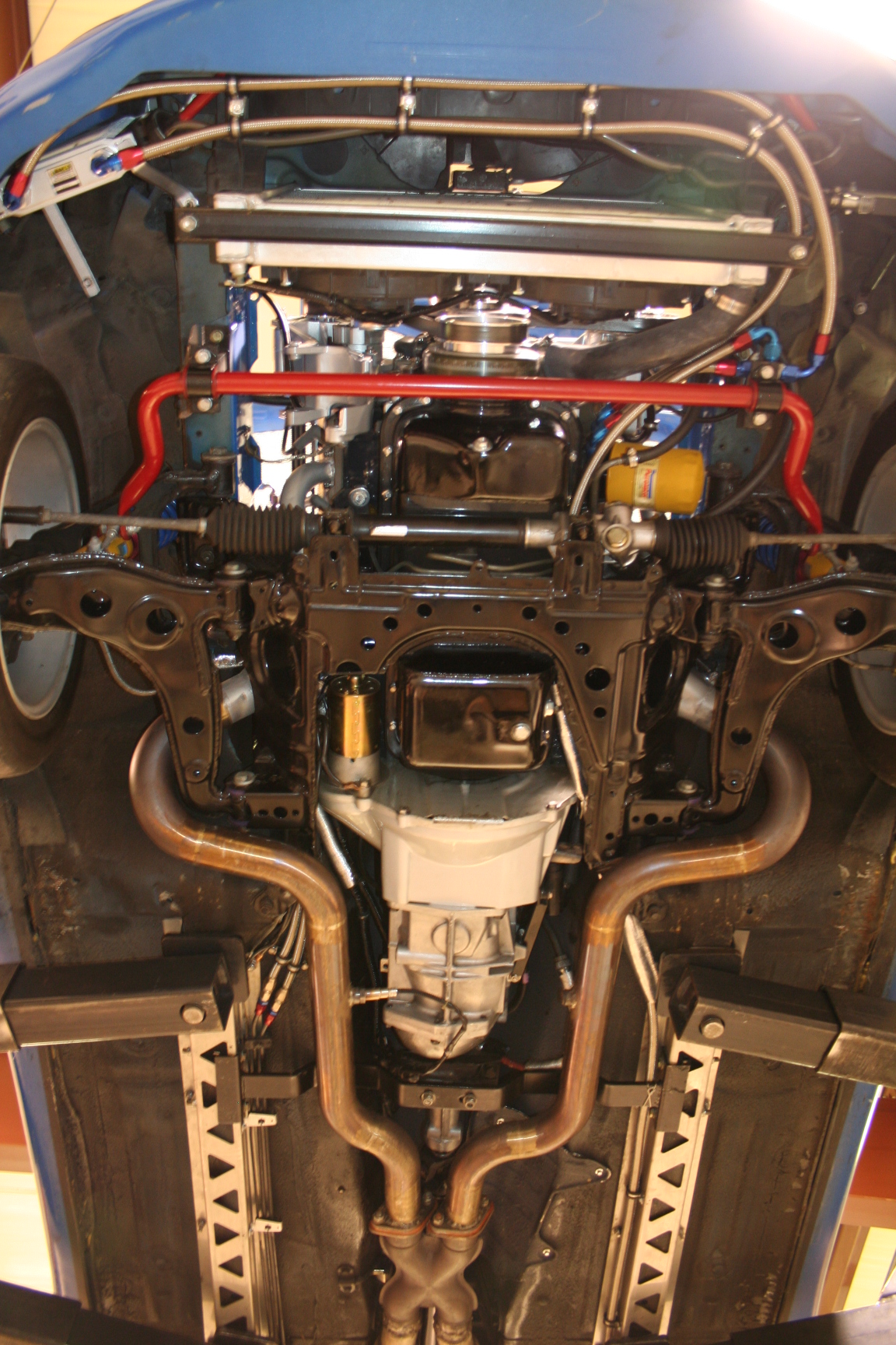
7/27/10 It's been a long time since
the last update, but I've made a lot of changes.
During the first autocross, I had some of
the power steering fluid to foam up and blow out of the reservoir.
At the time, I had no fluid cooler so I plumbed in a Perma-cool
1007. It's 5 inches by 7.5 inches, and 3/4 inches thick. I
mounted it in the driver side air pocket opening of the Racing Beat nose
with some brackets I made. I have not autocrossed or tracked the
car yet so I'm not sure if it helped the problem or not. I have
heard that due to the nature of the reservoir of the 94-95 Ford Mustang
pump, the neck is not real tall, it doesn't seal real well and the fluid
foams in high lateral forces and when worked hard. One trick is to
cut and extend the neck higher, but I haven't tried that yet. The
idea is to get more fluid in there to keep air bubbles getting into the
pump, as well as adding in more fluid to distribute the heat.
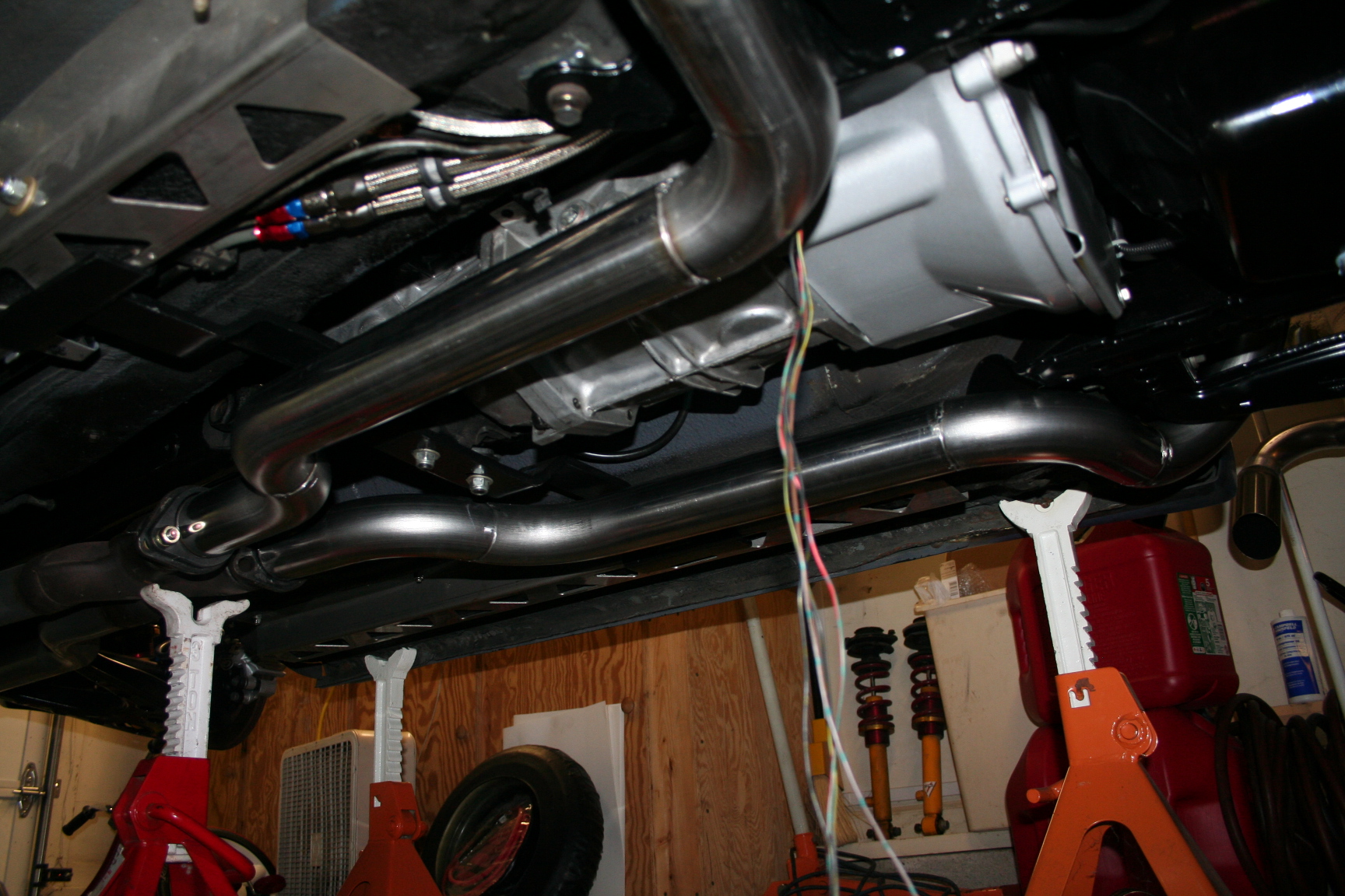
I plumbed in two small resonators and
rebuilt exhaust pipes w/ all stainless mandrel pipes going from the
x-pipe to the tips. It's a little quieter but not by a lot.
I'm glad it didn't get too quiet, but I'm surprised it wasn't quieter.
I removed the MSD 6AL and replaced it
with a Programmable MSD 6AL-2. The distributor is now locked
down so it does none of the ignition advance. In conjunction
with a 1-bar MAP sensor I installed, I now have the MSD 6AL-2
doing all of the advance that a mechanical/vacuum distributor
would do, but now adjustable through a laptop. Sort of 1/2
way to an EFI ignition/computer controlled setup.
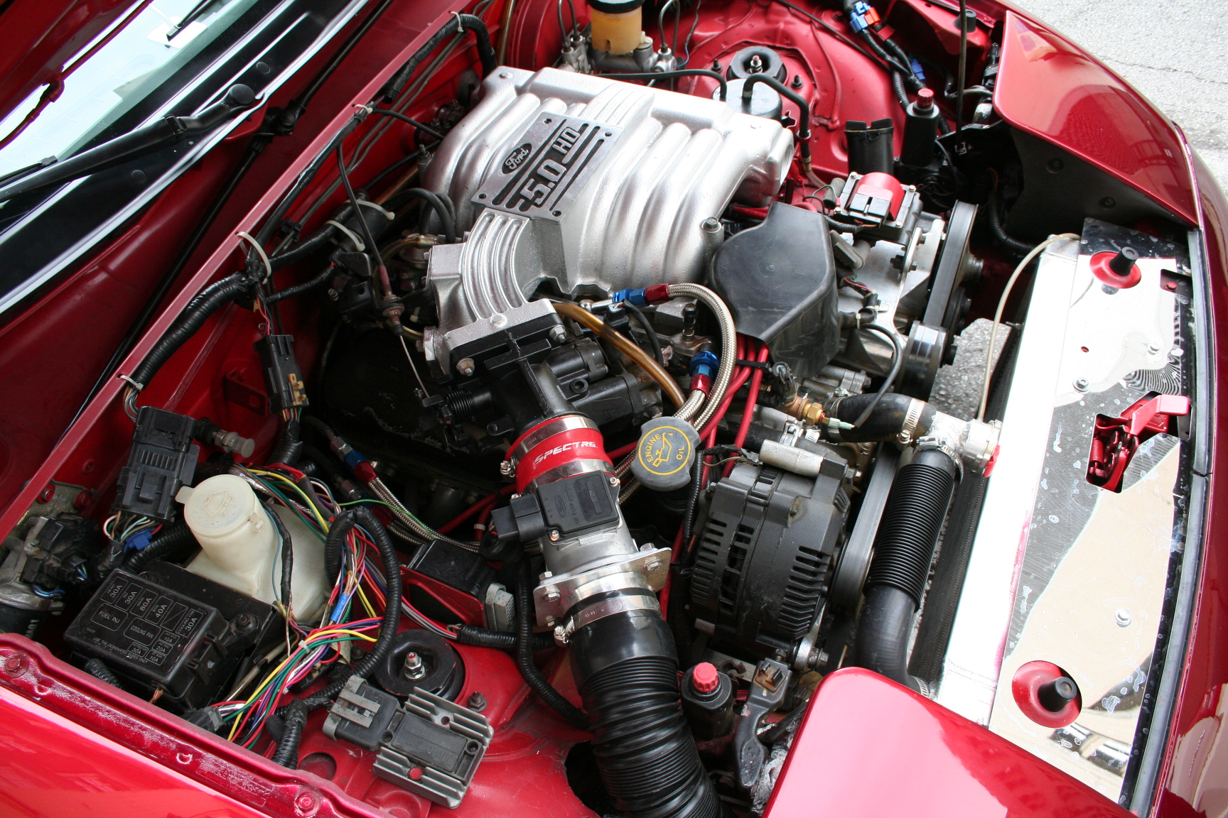
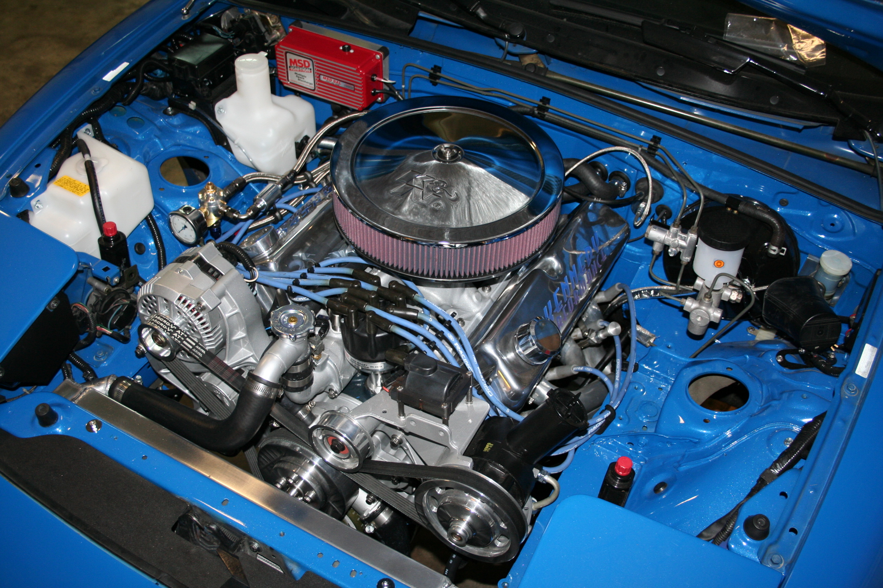
The plug wires are now clamped in place
with wire holders so they no longer drape over the side of the engine
bay. Neatened it up a bit and hopefully prevents the wires of
getting damaged.
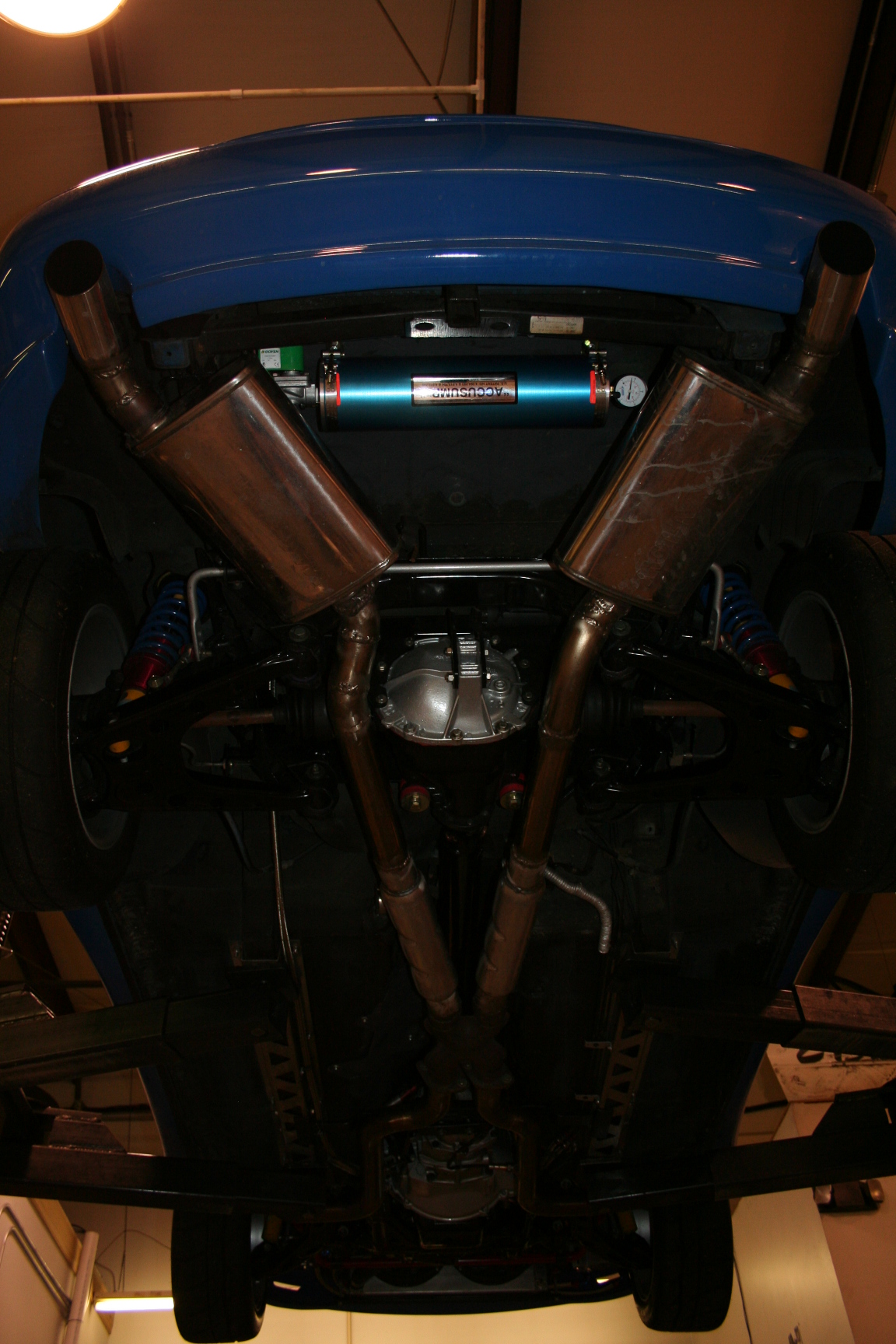
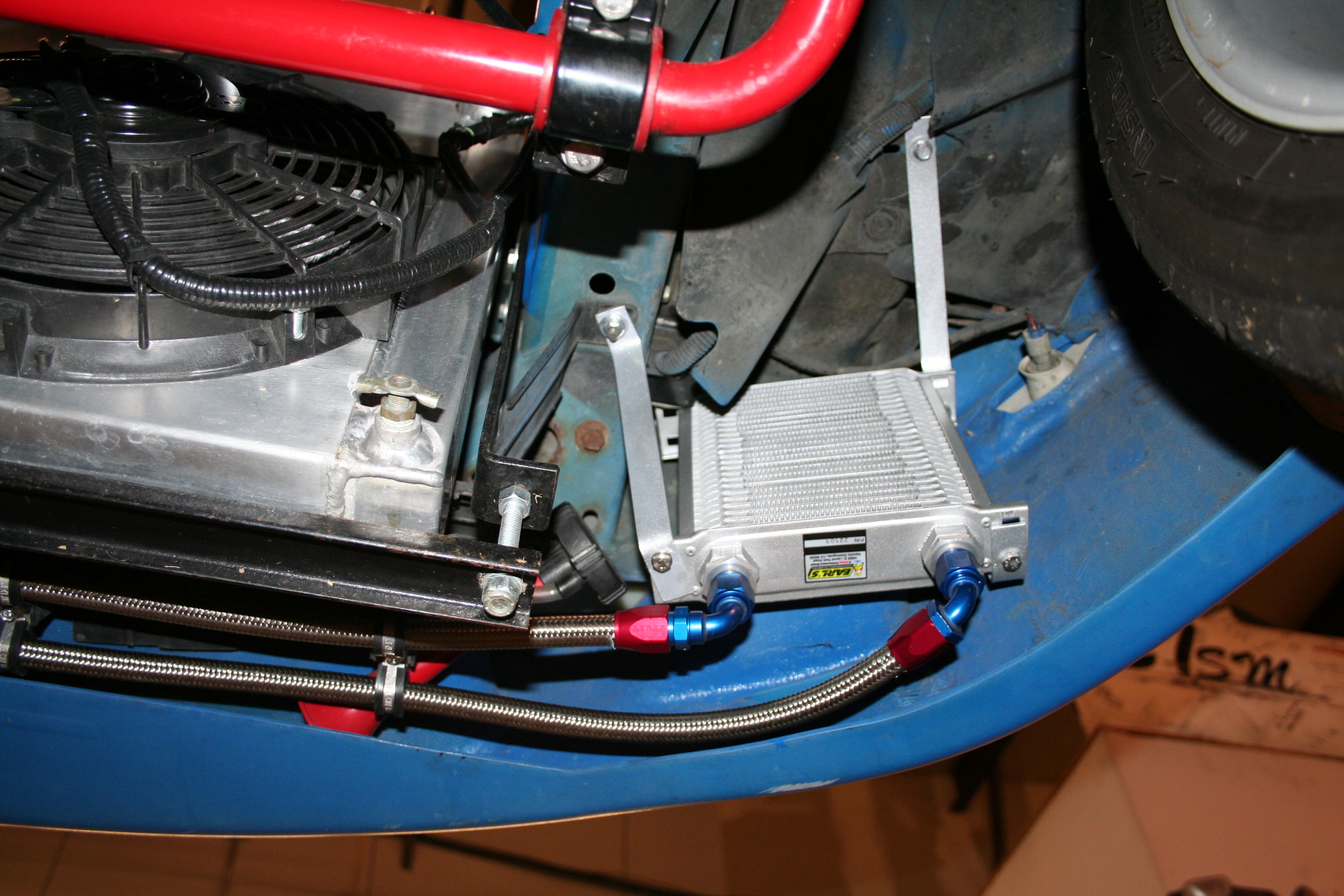
I also just finished an install of a 3
quart Accusump and oil cooler earlier today. The cooler is an
Earl's 22508ERL. It's about 8
inches by 8 inches and 2 inches thick. I mounted this in the
passenger side air pocket opening of the Racing Beat nose. A
before and after drive (yesterday w/o the cooler and then today w/ the
cooler) suggests it's dropping the peak oil temp from about 240 degrees
F to 220 degrees F. It was a little cooler outside today by about
10 degrees F so that might account for some of the difference.
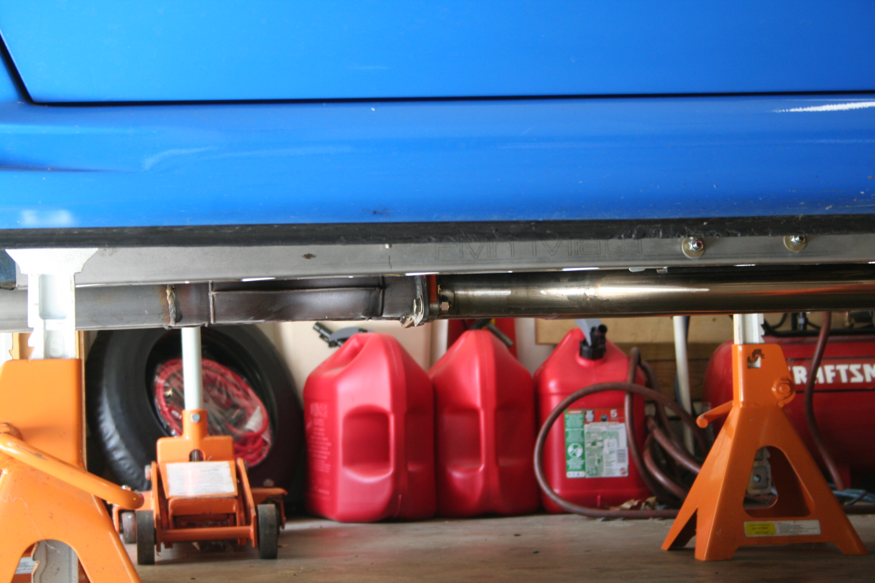
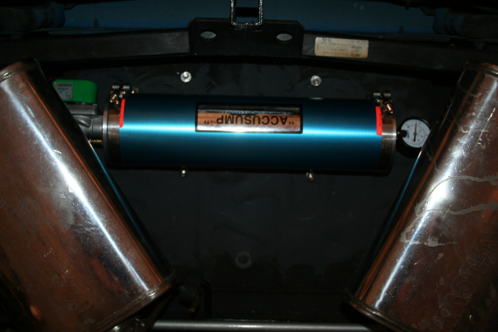
After debating where to locate the Accusump, I chose to mount it under
the trunk, between the mufflers. I was first worried about heat,
but after a good drive, I've found it's not really too hot. My
Accusump is a 3qt model, but I'm not sure how much oil it actually
contains. I used the electronic control valve that has a 20-25psi
sensor on it. Once the pressure drops below that level (sensed
between the valve and engine), it opens the valve allowing oil to pump
from the Accusump to the oil lines going to the oil cooler. As an
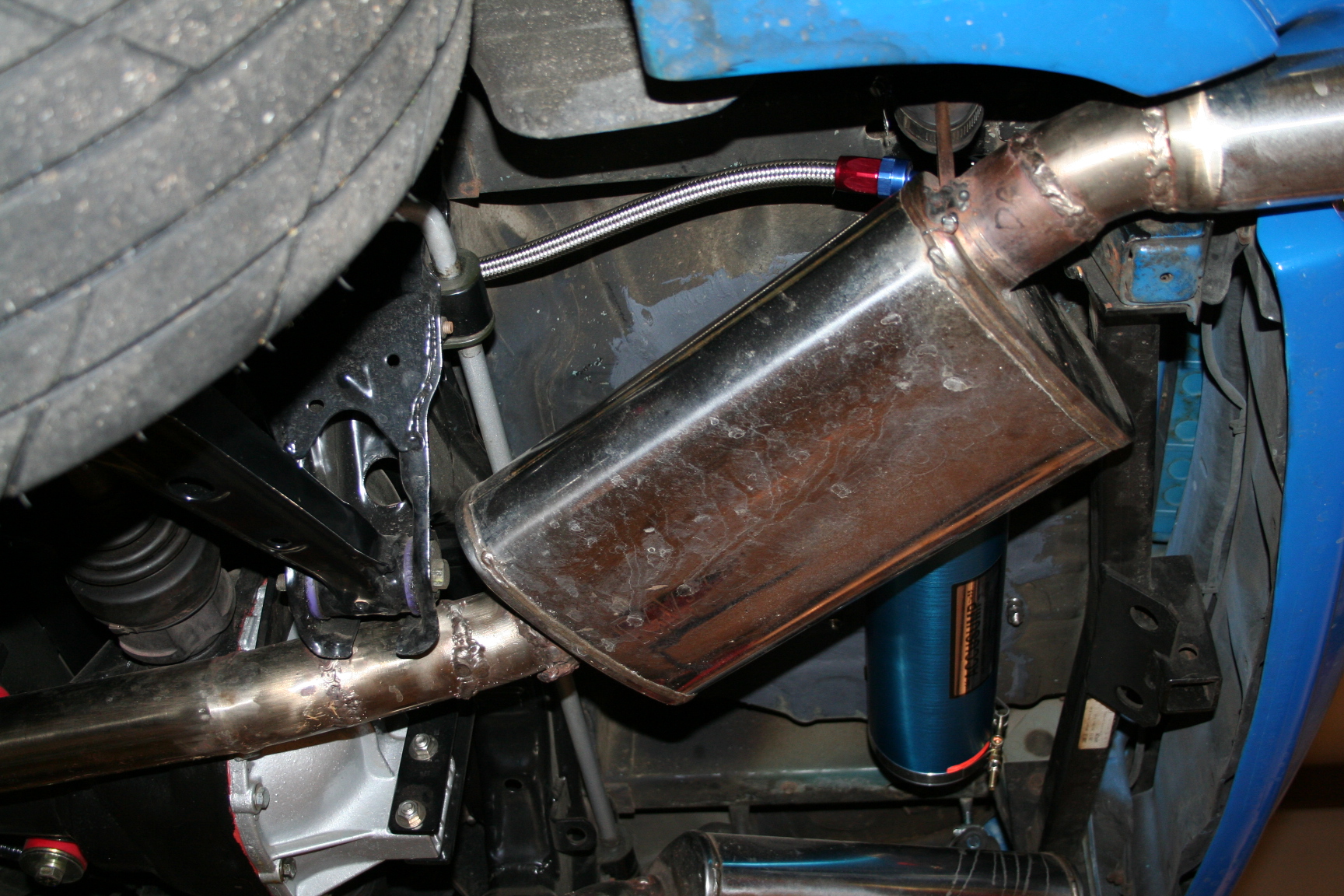
effort to prevent damage to the Accusump body (from road debris), I
bought some material to box in a shield around the sump. It's not
in yet, but will be added soon. The overall capacity of this
system went from 4qts to 7qts. I think that there is about 0.5 to
1 qt in the cooler and lines connecting it to the engine, and another 2
to 2.5 in the Accusump and line going to it. I used a total of 19
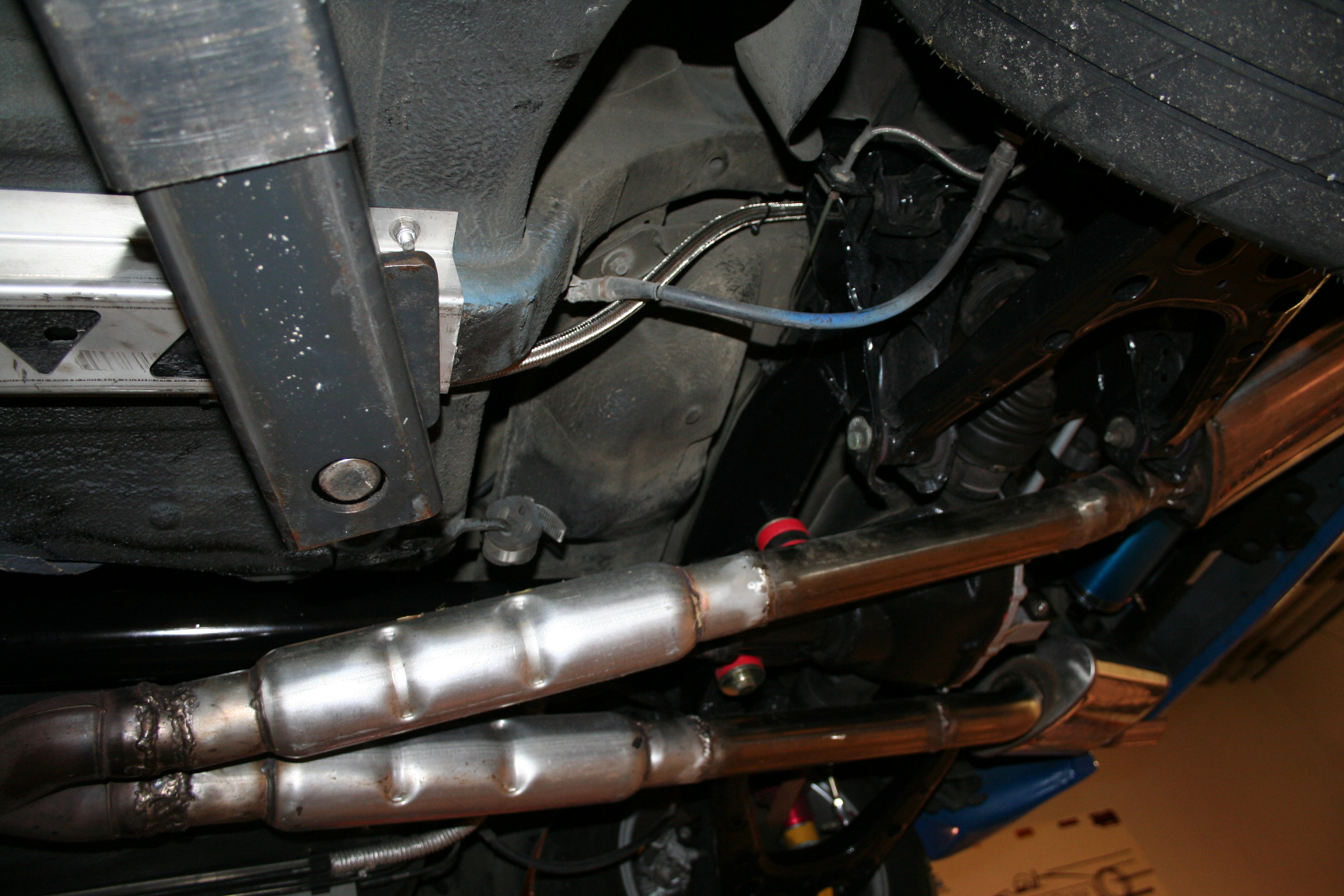
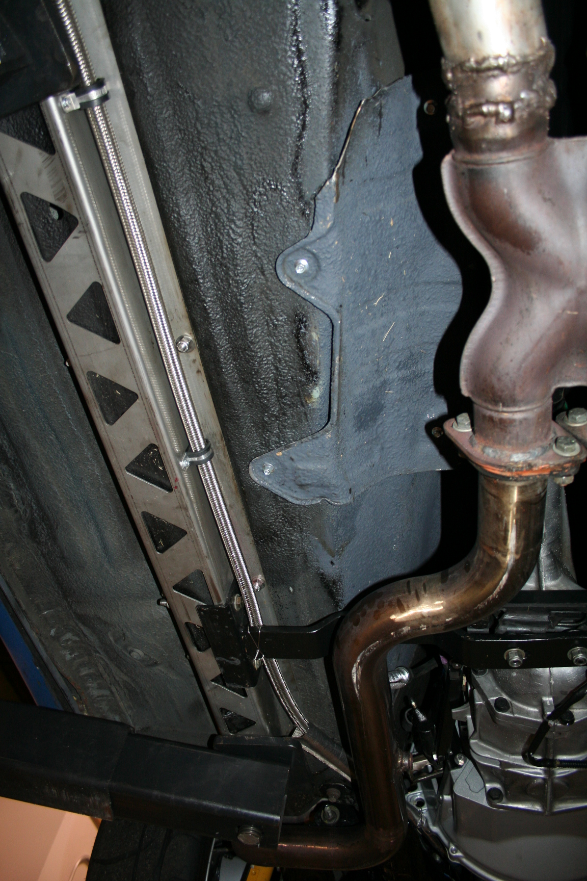
feet of -8AN line to plumb it all in, including the cooler.
Fittings and routing the lines were a little tricky, but it's in.
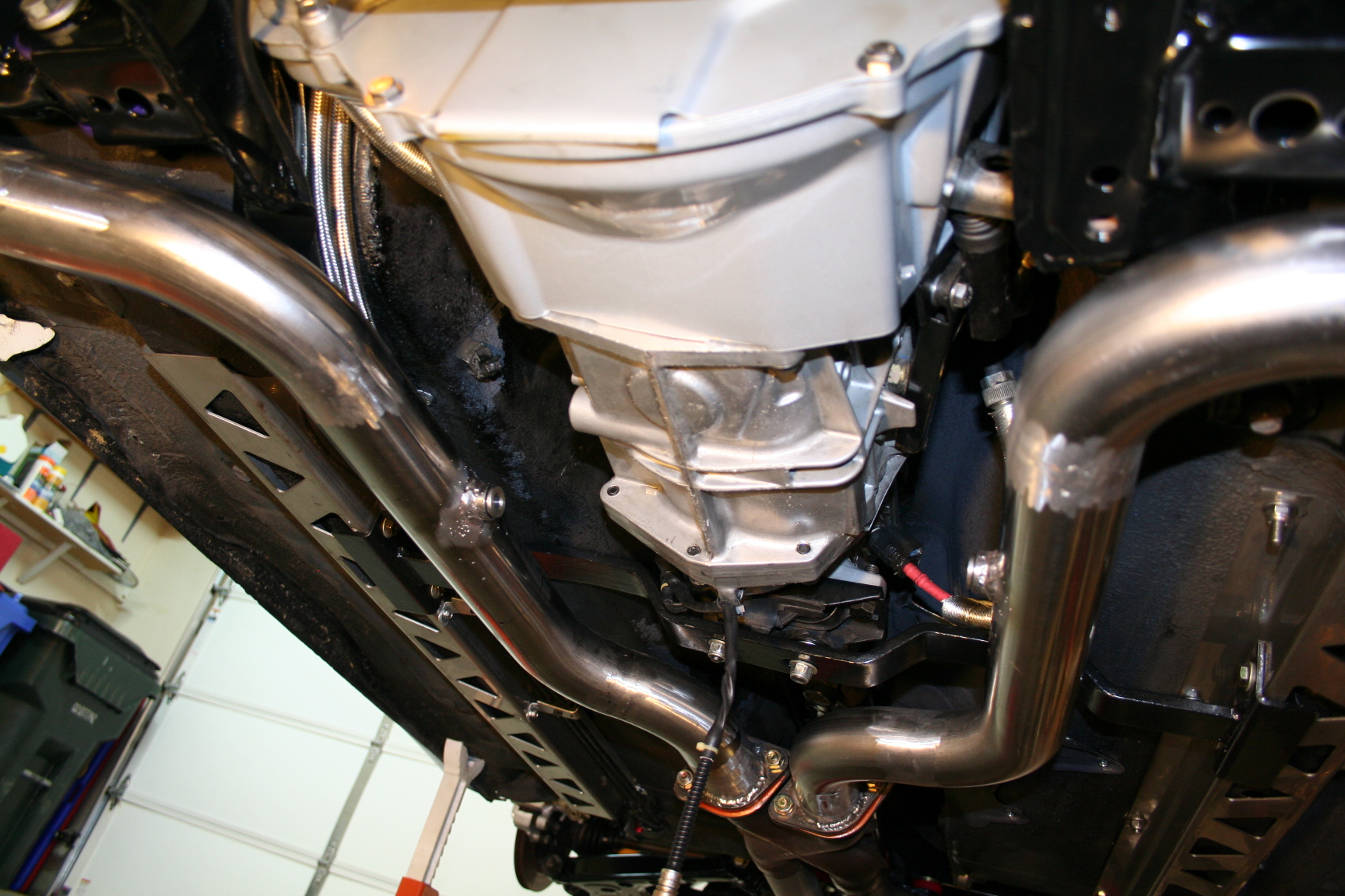
The line going to the Accusump tucks between the oil pan and engine
mount pedestal, over the exhaust header (shielded partially by the
K-frame and with some Thermotec hose sleeve, then down along the frame
rail, over the rear subframe and connected to the valve of the Accusump.
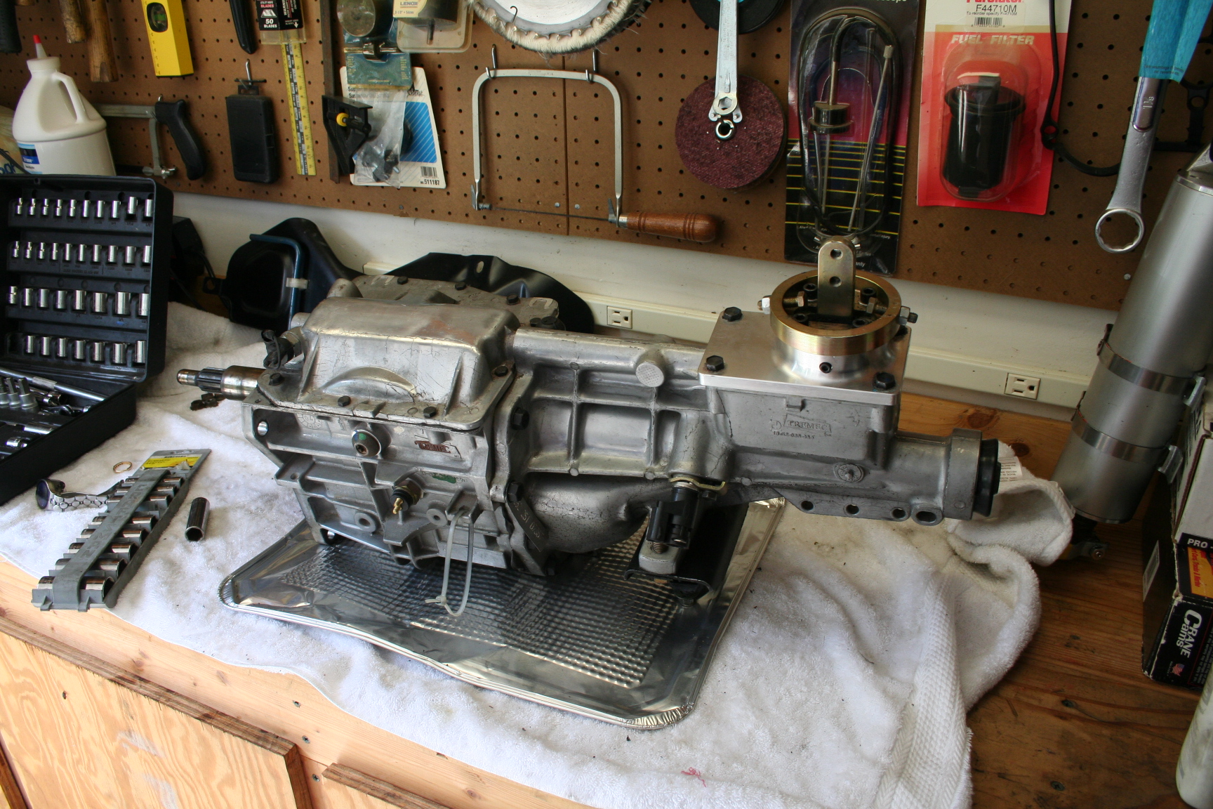
I rebuilt my T5Z
transmission with all new synchro's, bearings, etc... reinforced the
countershaft bearing with a steel retainer, and changed the 5th gear set
from 0.63 to 0.73. Much better fit for 5th gear! I was going
to go to 0.80 but was advised by the retailer that 0.73 would be better
for my application since I'm mostly on the street. There is no
more gear noise that before and 5th just seems to about right where it
needs to be now. The rebuild was a major task. I took a lot
of pictures and followed steps in books and online so it would go back
together. I was very nervous but it worked.
 from my friends on
miata.net
and other Ford forums, friends in the local miata community, friends at work, local
machine shops/garages/speed shops, and basic research from reading up on
302 Windsor based blocks. My basic goal is to achieve at least
325hp to the ground (about 375 at the crank) while equipping the car for decent street manners
yet reliable enough to withstand occasional track time. Oh... and
it's gotta have that classic V8 sound.
from my friends on
miata.net
and other Ford forums, friends in the local miata community, friends at work, local
machine shops/garages/speed shops, and basic research from reading up on
302 Windsor based blocks. My basic goal is to achieve at least
325hp to the ground (about 375 at the crank) while equipping the car for decent street manners
yet reliable enough to withstand occasional track time. Oh... and
it's gotta have that classic V8 sound.